background image

Software Setup

4-41

VIA Fast InfraRed Device Driver installation for Windows
ME

1. Put the supplied CD into the CD ROM drive and double click “

System

in the “

Control Panel

”.

2. The “

System Properties

” window is popped. Select the “

Device

Manager

” tab (left click the tab), then select the “

PCI Ethernet Control

and click the “Properties” button.
3. In the “

Unknown Device Properties

” window. Select “

General

” tab

and click the “

Reinstall Driver

” button.

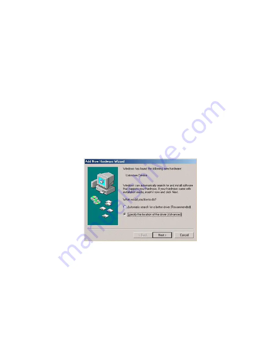
4. The “

Update Device Driver Wizard

” is invoked. Select “

Specify

the location of the driver [Advanced]

” and click the “

Next

” button.

Содержание EPIA-5000 - VIA Motherboard - Mini ITX

Страница 1: ...i Version 1 0 March 21 2002 VIA User s Manual VIA EPIA Mini ITX Mainboard P N 99 51 010061...

Страница 2: ...cy of the content of this manual However it is possible that it may contain technical inaccuracies or typographical or other errors VIA will assume no liability for any inaccuracy found in this public...

Страница 3: ...tion manual may cause harmful interference to radio communications Operation of this equipment in a residential area is likely to cause harmful interference in which case the user will be required to...

Страница 4: ...dule 9 All cautions and warnings on the equipment should be noted 10 Never pour any liquid into the opening Liquid can cause damage or electrical shock 11 If any of the following situations arises get...

Страница 5: ...PIA Mini ITX Mainboard package should contain the following items 1 x VIA EPIA Mini ITX Mainboard 1 x User s manual 1 x ATA 33 66 100 Hard drive ribbon cables 1 x Driver Utilities CD 1 x I O Bracket B...

Страница 6: ...19 3 BIOS Setup 3 1 Entering Setup 3 2 Control Keys 3 2 Getting Help 3 3 The Main Menu 3 4 Standard CMOS Features 3 6 Advanced BIOS Features 3 8 Advanced Chipset Features 3 11 Integrated Peripherals 3...

Страница 7: ...vii 4 Software Setup 4 1 VIAApollo PLE133 Chipset Drivers 4 2 VIA PLE133 Integrated VGA Driver 4 12 VIAAudio Driver 4 14 VIA Network Driver 4 15 VIA Fast InfraRed Device Driver 4 30...

Страница 8: ...ITX mainboard enables the creation of an exciting new generation of small ergonomic innovative and affordable embedded systems Through high levels of integration mini ITX only occupies 66 of the size...

Страница 9: ...Trident Blade 3D graphics core Audio VT1612A AC 97 Codec 3 Audio jacks Line in Line out and Mic in Main Memory 2 x PC100 133 DIMM slots PCI Bus IDE Supports up to 4 IDE devices Ultra DMA 33 66 100 LA...

Страница 10: ...600 NTSC PAL TV S Video or RCA Video output I O Ports 1 PS2 Mouse connenctor 1 PS2 Keyboard connector 1 15 pin External Monitor connector 1 16C550 compliant serial port 1 EPP ECP complaint parallel p...

Страница 11: ...Chapter 1 1 4 VIA EPIA Mini ITX Mainboard Note Onboard DOC is optional Layout...

Страница 12: ...s See p 2 8 RCA Video or S P DIF Connecting to RCA Video or SPDIF See p 2 8 S Video Connecting to S Video See p 2 8 CRT connector Connect to CRT monitor See p 2 8 IDE 1 IDE 2 Connecting IDE devices Se...

Страница 13: ...mponents can be damaged if installed incorrectly If possible use a grounded wrist strap before handling computer components The components can be damaged by static electricity This chapter contains th...

Страница 14: ...the connection of a CPU fan and an additional system case fan CPU CPU Fan Cable CPU Fan Heatsink CPU Fan Connector The VIA C3TM E Series Processor With low power consumption and advanced thermal dissi...

Страница 15: ...fications is not recommended We do not guarantee the damages or risks caused by operation beyond product specifications WARNING The VIA Eden Processor Providing ultra low power consumption and advance...

Страница 16: ...dules will only fit if placed in the correct position 2 With both hands press the SDRAM module down into the DIMM slot so that the white retaining latches rotate up and secure the module in place see...

Страница 17: ...DIMM 1 32MB 64MB 128MB 256MB 512MB 32MB 512MB DIMM 2 32MB 64MB 128MB 256MB 512MB 32MB 512MB Maximum System Memory Supported 1GB Available SDRAM Configurations Refer to the table below for available SD...

Страница 18: ...ientation and the pins are correctly aligned Then push down the power supply plug firmly into the connector The VIA EPIA Mini ITX Mainboard requires an ATX power supply to be connected Before insertin...

Страница 19: ...S 2 Mouse You can connect a PS 2 mouse directly to this standard PS 2 mouse connector PS 2 Keyboard The mainboard provides a standard PS 2 keyboard connector for connecting a PS 2 keyboard LPT Connect...

Страница 20: ...t devices such as a keyboard mouse or digital camera RCA Video or S P DIF Port This dual function port may be used either as a RCA Video port or as a S P DIF port An onboard jumper J11 allows you to s...

Страница 21: ...ter and a slave drive allowing a maximum of four seperate devices such as a HDD CD ROM or CD RW to be connected Also a Disk on Module can be connected directly to one of the IDE connectors These conne...

Страница 22: ...allows you to connect and receive audio input from a device such as a CD ROM 12 1 1 1 2 Power Switch Reset Power LED L G G R 1 HDDLED Front Panel Connectors J3 The J3 front panel connectors allow you...

Страница 23: ...andard module This is not for standard FIR module for reference design please consult with VIATechnologies Inc CIR Module Connector J6 TheCIRModuleConnector J6 allowsyoutoconnectaConsumerInfrared stan...

Страница 24: ...gh the modem USB Port 2 3 Connector J9 This connector J9 allows you to connect an additional two Universal Serial Bus USB ports in case the two USB ports on the back panel are not sufficient To utiliz...

Страница 25: ...ows you to connect an external video source The PCI Riser Card Connector left part of J12 see diagram below allows you to connect a PCI Riser Card module These connectors are not for standard Video In...

Страница 26: ...OS Jumper to clear data Follow the instructions below to clear the data The VIA EPIA Mini ITX Mainboard provides a series of jumpers to set the computer s functions This section explains the functions...

Страница 27: ...d The three available options are 66MHz 100MHz and 133MHz J13 Host Frequency Select Overclocking This motherboard is not designed to support overclocking Any attempt to operate beyond product specific...

Страница 28: ...bles theAuto Reboot Function Setting When enabled the system will automatically reboot in the event of sudden power outage 1 1 2 Disable 2 3 Enable CPU Strapping Function Setting J1 This jumper enable...

Страница 29: ...standard option on this mainboard and is a manufacturing option only Therefore the DOC function may not be present on the mainboard you have purchased 1 1 2 Disable 2 3 Enable RCA Video or S P DIF Sel...

Страница 30: ...unplug the power supply first Meanwhile read the documentation for the expansion card to make any necessary hardware or software settings for the expansion card such as jumpers switches or BIOS config...

Страница 31: ...chanism for devices to request services from the microprocessor The PCI LAN IRQ pins are typically connected to the PCI bus INT A INT D pins as follows PCI Interrupt Request Routing Order 1 Order 2 Or...

Страница 32: ...lp 3 3 The Main Menu 3 4 Standard CMOS Features 3 6 Advanced BIOS Features 3 8 Advanced Chipset Features 3 11 Integrated Peripherals 3 15 Power Management Setup 3 20 PNP PCI Configurations 3 26 PC Hea...

Страница 33: ...re tu rn s to th e m a in m e n u fro m a s u b m e n u P U In c re a s e th e n u m e ric v a lu e o r m a k e c h a n g e s P D D e c re a s e th e n u m e ric v a lu e o r m a k e c h a n g e s F...

Страница 34: ...ram provides a General Help screen You can call up this screen from any menu sub menu by pressing F1 The help screen displays the keys for use and navigate the BIOS setup Press Esc to exit the help sc...

Страница 35: ...ific features and optimize system performance Integrated Peripherals Use this menu to set onboard peripherals features Power Management Setup Use this menu to set onboard power management functions Pn...

Страница 36: ...perations Load Optimized Defaults Use this menu to load BIOS default settings for optimal and high performance system operations Set Supervisor Password Use this menu to set supervisor password Set Us...

Страница 37: ...the video mode Available options are EGA VGA CGA 40 CGA 80 and Mono Halt On Determine the system behaviour if an error is detected during bootup Settings All Errors System halts when any error is det...

Страница 38: ...he hard disk will not work properly if you enter improper information for this category SelectAuto whenever possible If you select Manual make sure the information provided is from your hard disk vend...

Страница 39: ...CPU L2 Cache Settings Enabled and Disabled CPU L2 Cache ECC Checking Set the ECC Error Correcting Code feature for Level 2 cache Facilitates error detection correction when data passes through Level 2...

Страница 40: ...system to boot from other devices if the system fails to boot from the First Second Third boot device Settings Enabled and Disabled Boot Up NumLock Status Set the NumLock status when the system is po...

Страница 41: ...e CC000 CFFFF region Settings Disabled and Enabled D0000 D3FFF Shadow Enable shadow in the D0000 D3FFF region Settings Disabled and Enabled D4000 D7FFF Shadow Enable shadow in the D4000 D7FFF region S...

Страница 42: ...o 16M area Settings Disabled and 15M 16M System BIOS Cacheable Cache the System Bios Settings Disabled and Enabled Video RAM Cacheable Cache the Video RAM Settings Disabled and Enabled TV Standard Set...

Страница 43: ...en appears DRAM Clock Set the DRAM Clock Settings Host CLK HCLK 33M and By Auto DRAM Timing By SPD Set DRAM Timing by SPD Settings Disabled and Enabled SDRAM Cycle Length Set the SDRAM Cycle Length Se...

Страница 44: ...d the following screen appears AGP Aperture Size Set theAGPAperture Size Settings 256M 128M 64M 32M 16M 8M and 4M AGP Master 1 WS Write Set the AGP Master 1 WS Write Settings Disabled and Enabled AGP...

Страница 45: ...ngs Disabled and Enabled CPU to PCI Write Buffer Set the CPU to PCI Write Buffer Settings Disabled and Enabled PCI Dynamic Bursting Set the PCI Dynamic Bursting Settings Disabled and Enabled PCI Maste...

Страница 46: ...ffer size Settings 2M 4M and 8M OnChip USB Set the state of the OnChip USB Settings Enabled and Disabled USB Keyboard Support This setting specifies whether it is neccessay for BIOS to provide support...

Страница 47: ...the fast block mode to transfer data to and from the hard disk drive Block mode is also called block transfer multiple commands or multiple sector read write Enabled enables IDE controller to use bloc...

Страница 48: ...Chip PCI Device Press Enter to enter the sub menu and the following screen appears VIA 3058 AC97 Audio Set the VIA 3058 AC97 Audio codec Auto automatically detect the presence of audio codec Disabled...

Страница 49: ...t the Sound Blaster DMA channel Settings DMA 0 DMA 1 DMA 2 and DMA 3 MPU 401 Set the MPU 401 option Settings Disabled and Enabled MPU 401 I O Address Set the MPU 401 I OAddress Settings 300 303H 310 3...

Страница 50: ...llel port as Standard Parallel Port choose Normal To operate the onboard parallel port in the EPP mode choose EPP By choosing ECP the onboard parallel port will operate in ECP mode Choosing ECP EPP wi...

Страница 51: ...st and hardware maintains all system context S3 STR S3 Suspend To RAM STR is a power down state In this state power is supplied only to essential components such as main memory and wakeup capable devi...

Страница 52: ...video off Settings Blank Screen V H SYNC Blank and DPMS Support Modem Use IRQ Select the IRQ use by modem Settings NA 3 4 5 7 9 10 and 11 Soft Off by PWRBTN This field configures the power button fun...

Страница 53: ...consumption Settings User Define Min Saving and Max Saving HDD Power Down The HDD power down timer Settings Disable 1 15Min Doze Mode Set the doze mode Only available if Power Management function is...

Страница 54: ...her to enable PS2 Mouse wakeup function Settings Disabled and Enabled USB Resume from S3 Decide whether or not the USB devices can wake the system from S3 Settings Disabled and Enabled VGA Decide whet...

Страница 55: ...uspend state Such PCI cards include LAN onboard USB ports etc Settings Disabled and Enabled Modem Ring Resume Decide whether or not Ring In signals from Modem can wake up the system from suspend state...

Страница 56: ...ecified IRQ line If set to Enabled the activity of the specified IRQ line will prevent the system from entering power saving modes or awaken it from power saving modes Note IRQ Interrupt Request lines...

Страница 57: ...ialize all the PnP cards Set to Yes the operating system is Plug Play capable The settings No and Yes Reset Configuration Data Normally you leave this field Disabled Select Enabled to reset Extended S...

Страница 58: ...ettings Auto ESCD and Manual IRQ Resources The items are adjustable only when Resources Controlled By is set to Manual Press Enter and you will enter the sub menu of the items IRQ Resources list IRQ 3...

Страница 59: ...ntrolled By is set to Manual Press Enter and you will enter the sub menu of the items Resources list DMA 0 1 3 5 6 7 for users to set each DMA channel type Settings PCI ISA PnP For Plug Play compatibl...

Страница 60: ...s of your CPU fan warning for overall system status CPU Fan Speed CPU Fan 2 Speed 12V 5V 2 5V Vcore and Internal VCC These items display the current status of all of the monitored hard ware devices co...

Страница 61: ...default Fail Safe values These values are set by the mainboard manufacturer to provide the most stable system When you select Load Fail Safe Defaults a message as below appears Pressing Y loads the de...

Страница 62: ...mized Defaults are the default values also set by the mainboard manufacturer for both optimized and stable performance of the mainboard When you select Load Optimized Defaults a message as below appea...

Страница 63: ...ord will be disabled Once the password is disabled the system will boot and you can enter Setup without entering any pass word When a password has been set you will be prompted to enter it every time...

Страница 64: ...word Supervisor password Can enter and change the settings of the setup menus User password Can only enter but do not have the right to change the settings of the setup menus Setup If set to Setup pas...

Страница 65: ...you can select this option to save the changes and quit Amessage as below will appear on the screen Typing Y will allow you to quit the Setup Utility and save the user setup changes to RTC CMOS Typing...

Страница 66: ...enu you can select this option to abandon the changes A message as below will appear on the screen Typing Y will allow you to quit the Setup Utility without saving any changes to RTC CMOS Typing N wil...

Страница 67: ...LE133 Chipset Drivers 4 2 VIA PLE133 Integrated VGA Driver 4 12 VIA Audio Driver 4 14 VIA Network Driver 4 15 VIA Fast InfraRed Driver 4 30 Note You must install VIA 4in1 chipset driver first before i...

Страница 68: ...he VIA PLE133 chipset is a highly integrated cost effective and energy efficient SMA chipset Featuring the Apollo PLE133 graphics controller with highly integrated display control device that includes...

Страница 69: ...show two installation options Select Normally Install to manually install every driver else select Quickly Install to install the drivers automatically Click Next to continue for Quickly Install users...

Страница 70: ...tall VIA PCI IDE Bus Driver Please select the driver and click on Next to continue 9 After all chipset drivers are properly installed please select Yes I want to restart my computer now and click Fini...

Страница 71: ...e VIA Service Pack 4 4 When the installation starts click Next to view the VIA Service Pack README 5 Click Yes to proceed 6 The screen now will show two installation options Select Normally Install to...

Страница 72: ...lick Next to continue 9 Select Install AGP 4X 133 driver and click Next to continue 10 After all chipset drivers are properly installed please select Yes I want to restart my computer now and click Fi...

Страница 73: ...e CD should run automatically and the setup screen will appear If not please run the setup exe within the CD manually 3 On the setup screen click on the Install VIA Chipset Drivers option to install t...

Страница 74: ...else select Quickly Install to install the drivers automatically Click Next to continue for Quickly Install users please go to step 12 7 The screen will now show four drivers VIA ATAPI Vendor Support...

Страница 75: ...ck Next to continue 10 Select Install VIA AGP VxD in Turbo mode and click Next to continue 11 Select Install VIA IRQ Routing Miniport Driver and click Next to continue 12 After all chipset drivers are...

Страница 76: ...starts click Next to view the VIA Service Pack README 5 Click Yes to proceed 6 The screen now will show two installation options Select Normally Install to manually install every driver else select Qu...

Страница 77: ...ick Next to continue 10 Select Install VIA AGP VxD in Turbo mode and click Next to continue 11 After all chipset drivers are properly installed please select Yes I want to restart my computer now and...

Страница 78: ...D into the CD ROM drive 2 The CD should run automatically and the setup screen will appear If not please run the setup exe within the CD manually 3 On the setup screen click on the Install Integrated...

Страница 79: ...Software Setup 4 13 5 After the VGA driver is properly installed please select Yes I want to restart my computer now And click Finish to restart your computer and complete the installation...

Страница 80: ...cally and the setup screen will appear If not please run the setup exe within the CD manually 3 On the setup screen click the Install VIA Audio Driver 4 Select Install driver Click Next to continue 5...

Страница 81: ...nstallation for Windows XP 1 Put the supplied CD into the CD ROM drive and double click System in the Control Panel 2 The System Properties window is popped Select the Hardware tab And click the Devic...

Страница 82: ...ce Manager window is popped Then select the VIA PCI 10 100Mb Fast Ethernet Adapter and click right button to select the Properties 4 In the VIA PCI 10 100Mb Fast Ethernet Adapter Properties window sel...

Страница 83: ...Software Setup 4 17 5 Once the Update Device Driver Wizard is invoked Select Next to continue 6 Select Don t search I will choose the driver to install and click Next button to continue...

Страница 84: ...Select VIA PCI 10 100Mb Fast Ethernet Adapter for driver and click Have Disk to find driver location 8 Click Browse button to find driver location In this case the driver is in E DRIVERS LAN Then clic...

Страница 85: ...e Setup 4 19 9 Find the suitable device VIA 10 100Mb Fast Ethernet Adapter from the location E Drivers LAN and click Next button to continue 10 Complete upgrading the driver and click Finish to close...

Страница 86: ...s 2000 1 Put the supplied CD in the CD ROM drive and click the Start Setting and Control Panel sequentially And double click System 2 The System Properties window is popped Select the Hardware tab lef...

Страница 87: ...is popped Then select the Ethernet controller and click right mouse button and select the Properties 4 In the Ethernet Controller Properties window Select Reinstall Driver button 5 The Update Device D...

Страница 88: ...Chapter 4 4 22 6 Select Search for a suitable driver for my device recommended and click Next to continue 7 Select Specify a location for driver and click Next to continue...

Страница 89: ...nd driver location In this case the driver is in E DRIVERS LAN Then click OK to continue 9 Find the suitable driver from the location E Drivers LAN and click Next to continue 10 Completing the Upgrade...

Страница 90: ...the CD ROM drive and right click the My Computer icon on the desktop Move mouse pointer to Properties item and left click it 2 The System Properties window is popped Select the Device Manager tab lef...

Страница 91: ...ller Properties window click the Reinstall Driver button 4 The Update Device Driver Wizard is invoked then click Next to continue 5 Select Search for a better driver than the one your device is using...

Страница 92: ...Chapter 4 4 26 6 Click Browse to find driver location In this case the driver is in E DRIVERS LAN Then click Next to continue 7 Completing the Upgrade Device Driver and click Finish to close wizard...

Страница 93: ...ROM drive and right click the My Computer icon on the desktop Move mouse pointer to Properties item and left click it 2 The System Properties window is popped Select the Device Manager tab left click...

Страница 94: ...I 10 100Mb Fast EthernetAdapter Properties window select the Driver tab and click the Update Driver button 4 The Update Device Driver Wizard is invoked Select Specify the location of the driver Advanc...

Страница 95: ...se button to specify a location E DRIVERS LAN Then click Next to continue 6 Select The updated driver Recommended VIA PCI 10 100Mb Fast Ethernet Adapter to update new driver Then click Next to continu...

Страница 96: ...nstallation for Windows XP 1 Put the supplied CD into the CD ROM drive and double click System in the Control Panel 2 The System Properties window is popped Select the Hardware tab And click the Devic...

Страница 97: ...31 3 The Device Manager window is popped Then select the VIA Fast InfraRed Controller and click right button to select the Properties 4 In the VIA Fast InfraRed Controller Properties window select Upd...

Страница 98: ...Chapter 4 4 32 5 Once the Update Device Driver Wizard is invoked Select Next to continue 6 Select Don t search I will choose the driver to install and click Next button to continue...

Страница 99: ...33 7 Select VIA Fast InfraRed Controller for driver and click Have Disk to find driver location 8 Click Browse button to find driver location In this case the driver is in E DRIVERS FIR WINXP Then cli...

Страница 100: ...Chapter 4 4 34 9 Find the suitable device VIA Fast InfraRed Controller from the location and click Next button to continue 10 Complete upgrading the driver and click Finish to close wizard...

Страница 101: ...d Device Driver installation for Windows 2000 1 Put the supplied CD into the CD ROM drive and double click System in the Control Panel 2 The System Properties window is popped Select the Hardware tab...

Страница 102: ...window is popped Then select the Unknown device and click right button to select the Properties 4 In the Unknown device Properties window select Reinstall Driver button 5 The Update Device Driver Wiza...

Страница 103: ...Software Setup 4 37 6 Select Search for suitable driver for my device recommended and click Next to continue 7 Select Specify a location for driver Then click Next to continue...

Страница 104: ...ation In this case the driver is in supplied CD under E DRIVERS FIR WIN2000 Click OK to continue 9 Find the suitable driver from the location and click Next to continue 10 Completing the Upgrade Devic...

Страница 105: ...CD ROM drive and double click System in the Control Panel 2 The System Properties window is popped Select the Device Manager tab left click the tab then select the PCI Ethernet Control and click the P...

Страница 106: ...e one your device is using now Recommended and click Next to continue 6 Specify the location of the driver by clicking on Browse button The location should be E DRIVERS FIR WIN98SE Then click the Next...

Страница 107: ...System Properties window is popped Select the Device Manager tab left click the tab then select the PCI Ethernet Control and click the Properties button 3 In the Unknown Device Properties window Sele...

Страница 108: ...device is using now Recommended and click Browse to set the location to CD ROM drive under directory E DRIVERS FIR WINME Click Next to continue 6 Click Next in the Update Device Driver Wizard dialog...

Отзывы: