


AMOS
AMOS
AMOS
AMOS----3003
3003
3003
3003 User Manual
User Manual
User Manual
User Manual
13
2.7.
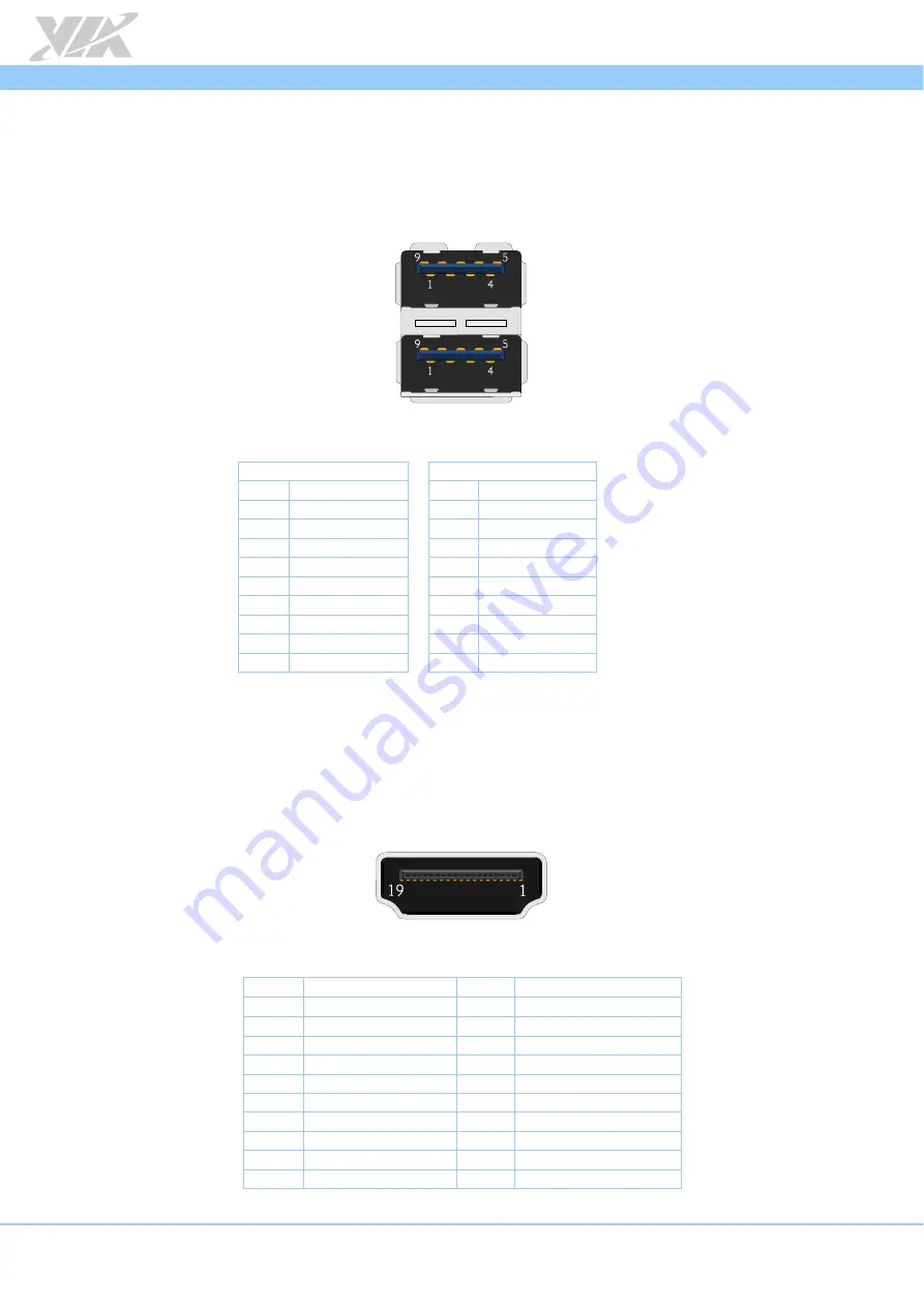
USB 3.0 Port
The AMOS-3003 is equipped with two USB 3.0 ports on the back panel. The USB 3.0 port has a maximum
data transfer rate up to 5Gbps and offers a backwards compatible with previous USB 2.0 specifications. Each
USB port gives complete Plug and Play and hot swap capability for external devices. The pinout of the
typical USB 3.0 ports are shown below.
Figure
Figure
Figure
Figure 14
14
14
14:
:
:
: USB 3.0 port
USB 3.0 port
USB 3.0 port
USB 3.0 portssss diagram
diagram
diagram
diagram
USB 3.0
USB 3.0
USB 3.0
USB 3.0 P
P
P
Port 1
ort 1
ort 1
ort 1
USB 3.0
USB 3.0
USB 3.0
USB 3.0 P
P
P
Port 2
ort 2
ort 2
ort 2
Pin
Pin
Pin
Pin
Signal
Signal
Signal
Signal
Pin
Pin
Pin
Pin
Signal
Signal
Signal
Signal
1
+5V
1
+5V
2
Data1-
2
Data2-
3
Data1+
3
Data2+
4
GND
4
GND
5
RX1-
5
RX2-
6
RX1+
6
RX2+
7
GND
7
GND
8
TX1-
8
TX2-
9
TX1+
9
TX2+
Table
Table
Table
Table 6
6
6
6:
:
:
: USB 3.0 port
USB 3.0 port
USB 3.0 port
USB 3.0 portssss pinout
pinout
pinout
pinout
2.8.
Mini HDMI
®
Port
The AMOS-3003 has a (19-pin) mini HDMI port on the back panel. The mini HDMI port uses an HDMI port
Type C receptable connector defined in HDMI specification. It is used to connect high definition video and
digital audio using a single cable. The pinout of the mini HDMI port is shown below.
Figure
Figure
Figure
Figure 15
15
15
15:
:
:
: Mini
Mini
Mini
Mini HDMI port diagram
HDMI port diagram
HDMI port diagram
HDMI port diagram
Pin
Pin
Pin
Pin
Signal
Signal
Signal
Signal
Pin
Pin
Pin
Pin
Signal
Signal
Signal
Signal
1
TMDS Data2 Shield
2
TMDS Data2+
3
TMDS Data2-
4
TMDS Data1 Shield
5
TMDS Data1+
6
TMDS Data1-
7
TMDS Data0 Shield
8
TMDS Data0+
9
TMDS Data0-
10
TMDS Clock Shield
11
TMDS Clock+
12
TMDS Clock-
13
DDC/CEC Ground
14
CEC
15
SCL
16
SDA
17
Reserved
18
+5V Power
19
Hot Plug Detect
Table
Table
Table
Table 7
7
7
7:
:
:
: Mini
Mini
Mini
Mini HDMI port pinout
HDMI port pinout
HDMI port pinout
HDMI port pinout
Содержание AMOS-3003
Страница 65: ......


