2
V
ersaPlanetary Quick Start Guide
Step 2:
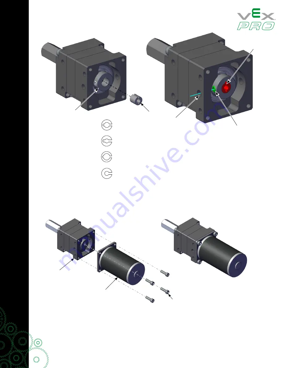
Insert the appropriate Collar into the Input Coupler as shown. Take note of the orientation of the Collar
(highlighted Red) and the Set Screw (highlighted green). The “split” in the Collar should align with the notch
in the Input Coupler as shown. The Set Screw should align with the Clearance Hole on side of the Input
Housing as illustrated by the blue line. DO NOT TIGHTEN THE SET SCREW.
Step 3:
To ensure Motor concentricity it is critical that the following processes are done in order.
1. Insert the Motor Output Shaft into the Collar. Take care not to rotate the Collar or the Input Coupler.
2. Mount the Step 1 Assembly with (4X) 8-32 x 1/2” Screws.
3. Use a 3/32” Hex Key to tighten the Set Screw.
4. Loosen the (4X) 8-32 x 1/2” Mounting Screws by about 1/4 turn.
5. Re-tighten the (4X) 8-32 x 1/2” Mounting Screws.
BAG Collar
RS-550 Collar
RS-775 Collar
AM-9015 Collar
Collar
Split and
Notch
Alignment
Set Screw
Clearance
Hole
Input
Coupler
Step 2
Step 1
8-32 x 1/2” screws (4X)


