Rev. 11/12/2018
OCC-2, MANUAL
Copyright 2017 Vestil Manufacturing Corp
5 of 7
Using the cylinder carrier:
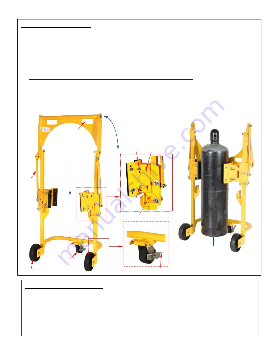
1. Move the carrier to the cylinder. Raise the handle to open/widen the clamp jaws.
2. Adjust position to put the cylinder inside the clamp, i.e. between the clamp jaws.
3. Apply the caster brake by pressing down on the brake lever.
4. Press the handle down. The cylinder should be firmly pressed between the clamp bumpers. When the
handle is all the way down, the cylinder should be elevated approximately 2 inches above the ground.
If the cylinder is not elevated when the handle is all the way down, then the clamp must be adjusted.
Each clamp jaw has a narrow setting (A) and a wide setting (B). Adjust the settings of both jaws so
that the cylinder is firmly clamped and automatically elevated when the handle is all the way down.
The handle must be pressed all the way down to securely grasp a cylinder
.
5. Release the caster brake. Grasp the hand holds and push the carrier to the desired location. The
carrier should only be used on even, level conrete or asphalt surfaces. Do not use the carrier on
inclines.
6. Apply the caster brake and release the cylinder by raising the handle.
Record of Normal Condition:
When the unit is first unpacked, make a written record of its appearance. Include observations about
hardware, welds, the frame, clamp jaws, caster and wheels, and linkages. Thoroughly photograph the
unit and all labels applied to it. Add the photographs to the record. Describe where each label is
located. Use the carrier to grasp, lift, and transport a cylinder. Describe the amount of force necessary
to move the handle, particularly to lock it (press it all the way down) and release it. Include descriptions
of sounds heard while applying and disengaging the clamp. This record establishes “normal condition”.
During future inspections, compare your observations to the record to determine if the unit is in normal
condition.
A
Handle
Clamp
jaw
Press handle all
the way down to
apply clamp and
lift cylinder
Center cylinder
between clamp
jaws
B
Clamping mechanism
automatically raises
cylinder ~2 inches above
the ground
Raise handle to
release cylinder
Brake lever
Hand
hold
Handle
linkage
Wheel
Locking
caster
Link arm
bolt
Link arm


