background image

Table of Contents


Rev. 4/22/2019 

   FMDL MANUAL 


Table of Contents


Copyright 2019   Vestil Manufacturing Corp.  


Page 5 of 16 


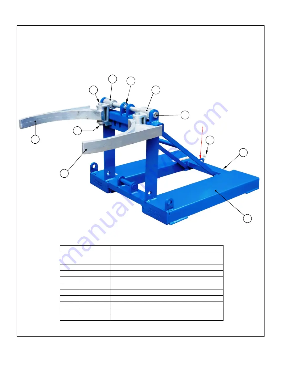
FPDL-11-H parts diagram and bill of materials 


Item 

Part No. 

Description 

40-514-008  Eagle Beak™ base frame casting 

40-514-016  Left side upper drum gripper  casting 

40-512-002  Left side hinge casting 

40-112-001  1 in. diameter 8-5/8 in. main clevis pin  

15-112-014  1 in. diameter x 4½ in. pin  

N/A 

Fork pockets 

65125 

3/16 in. x 1½ in. cotter pin 

37-145-004  5/16 in. x 48 in. chain 

65125 

3/16 in. x 1½ in. cotter pin 

10 

40-514-017  Right side upper drum gripper  casting 

11 

40-512-001  Right side hinge casting 

10 

11 

Quick link 

Содержание DFDL-3

Страница 1: ...andards applied where the product is used Technical Service and Replacement Parts For answers to questions not addressed in these instructions and to order replacement parts labels and accessories call our Technical Service and Parts Department at 260 665 7586 The department can also be contacted online at http www vestilmfg com parts_info htm Table of Contents Table of Diagrams Specifications 2 F...

Страница 2: ...r be beneath any part of the lifter or drum while it is elevated DO NOT use the lifter to transport anything but drums matched to your lifter See Specifications above Transport drums slowly Avoid rough terrain when transporting drums Jostling might disrupt the grasp on the rim DO NOT transport drums over rough terrain UNLESS they are secured to the lifter with a ratchet strap DO NOT modify the dru...

Страница 3: ...locking quick release 1 15 28 112 031 Pin clevis 3 4 x 41 4 2 5 09 145 018 5 16 chain 56 long 1 16 40 612 006 Weldment pin cradle retainer 1 6 08 145 041 Specialty hardware snap hook 5 16 1 17 40 514 011 Weldment pin bracket 1 7 33 112 023 Pin clevis 1 18 40 014 054 Weldment channel 1 8 40 145 008 Strap with ratchet 6 long 2 hooks 1 19 40 146 001 Spring tension 61 2 1 9 40 014 093 Drum cradle 1 20...

Страница 4: ...assembly 2 15 40 016 053 Lower jaw Eagle Beak 2 4 40 516 008 Weldment bracket mounting bar 1 16 40 514 011 Weldment pin bracket 2 5 65125 Cotter pin zinc plated 3 16 x 11 2 4 17 40 014 054 Weldment channel 2 6 99 112 004 Pin self locking quick release 2 18 28 112 031 Pin clevis 3 4 x 41 4 4 7 09 145 018 5 16 chain 56 long 1 19 40 612 006 Weldment pin cradle retainer 2 8 40 145 008 Specialty hardwa...

Страница 5: ...ing 2 40 514 016 Left side upper drum gripper casting 3 40 512 002 Left side hinge casting 4 40 112 001 1 in diameter 8 5 8 in main clevis pin 5 15 112 014 1 in diameter x 4 in pin 6 N A Fork pockets 7 65125 3 16 in x 1 in cotter pin 8 37 145 004 5 16 in x 48 in chain 9 65125 3 16 in x 1 in cotter pin 10 40 514 017 Right side upper drum gripper casting 11 40 512 001 Right side hinge casting 6 10 1...

Страница 6: ... head bolt 6 37018 in 20 UNC nylock hex nut 7 11219 in 13 UNC x 4 in hex head bolt 8 37030 in 13 UNC nylock hex nut 9 SPMSIRJ in outer diameter x in inner diameter 8 5 8 in axle sleeve tube 10 40 112 001 1 in diameter x 8 5 8 in main clevis pin 11 65125 3 16 in x 1 in cotter pin 12 40 514 021 Upper side wall support weldment 13 15 115 014 1 in diameter x 4 in retaining pin 14 N A Fork pockets 15 3...

Страница 7: ...y see items 4 9 16 17 on p 7 4 40 514 013 Left side lower drum gripper assembly see items 2 9 on p 7 5 40 514 014 Right side upper drum gripper assembly see items 5 9 11 on p 6 6 40 514 015 Left side upper drum gripper assembly see items 2 3 5 9 on p 6 7 n a Fork pocket 8 37 145 004 5 16 in x 48 in chain not shown 9 40 112 001 1 in diameter x 8 5 8 in main clevis pin 10 n a 3 16 in x 1 in cotter p...

Страница 8: ... inches from the outermost edges of the fork pockets dotted line in first graphic above Vertical center of gravity 65 16 inches 16 0 cm from the top of the fork pockets Horizontal center of gravity HCG 281 16 inches 71 3 cm from the open ends of the fork pockets middle graphic above and 205 8 52 4 cm from the outermost edges of the drum carrier dotted line in first graphic above Vertical center of...

Страница 9: ...of the fork pockets and 14 inches 36 2cm from the outer edge of each fork pocket halfway between the fork pockets Vertical center of gravity 9 inches 22 9cm from the bottom of the fork pockets Horizontal center of gravity HCG 24 inches 61cm from the open ends of the fork pockets and 14 inches 36 2cm from the outer edge of each fork pocket halfway between the fork pockets Vertical center of gravity...

Страница 10: ...of the fork pockets and 13 inches 33 7cm from the outer edge of each fork pocket halfway between the fork pockets Vertical center of gravity 11 inches 23cm from the bottom of the fork pockets Horizontal center of gravity HCG 25 inches 64 8cm from the open ends of the fork pockets and 13 inches 33 7cm from the outer edge of each fork pocket halfway between the fork pockets Vertical center of gravit...

Страница 11: ... drum and the drum is fully supported by the floor ground FPDL 11 H and DFDL 3 models Step 4 Position the fork lift and drum lifter Raise the forks and adjust the location of the fork lift to position the drum grippers above the top of the drum Tilt the mast forward i e point the forks toward the floor Step 5 Position drum grippers Lower the forks the drum grippers will slide over the lip of the d...

Страница 12: ... or ratchet strap loop castings are damaged 2 Labels all labels should be readable and located as shown in the Labeling Diagram If a label is unreadable or missing contact the Parts Department to order a replacement At least once per month inspect 1 Fasteners hardware Bolts nuts washers pins cotter pins Chain and snap hook 2 Fork pockets confirm that each pocket is structurally sound i e no signif...

Страница 13: ... 1 2 40 514 105 Frame subassembly 1 3 99 112 004 Pin self locking quick release 1 4 09 145 018 Chain 5 16 x 56 1 5 08 145 041 Snap hook 5 16 1 6 33 112 023 Pin clevis 1 7 65125 Cotter pin z plated 3 16 x 1 1 2 1 8 40 001 098 Saddle bumper belt assembly 1 Bumper belt subassembly exploded view provided on p 14 Item Part no Description Qty 1 40 514 008 Weldment frame 1 2 44 112 001 Pin main clevis 4 ...

Страница 14: ...1 2 13 4 9 40 145 014 Roller washer 4 5 37021 Nylock nut gr 2 zinc finish 5 16 18 6 10 40 612 011 Weldment pin belt 2 11 65078 Extended prong cotter pin z finish 1 8 x11 2 2 Drum Saddle Roller Subassembly 40 001 097 in Exploded Views on p 15 Item Part no Description Qty Item Part no Description Qty 1 40 145 012 Roller keel 3 6 65127 Cotter pin zinc plated 3 16 x 2 2 2 40 514 102 Weldment frame rol...

Страница 15: ...Pin clevis 1 7 65125 Cotter pin z plated 3 16 x 11 2 1 8 40 001 097 Drum saddle roller subassembly 1 Roller subassembly Exploded View provided on p 14 Item Part no Description Qty 1 40 514 008 Weldment frame 1 2 40 112 001 Pin clevis 4 3 40 514 105 Frame subassembly 2 4 40 516 008 Weldment bracket mounting bar 1 5 65125 Cotter pin z plated 3 16 x 11 2 4 6 99 112 004 Pin self locking quick release ...

Страница 16: ...draulic pumps motor controllers and cylinders It also covers defects in original parts that wear under normal usage conditions wearing parts such as bearings hoses wheels seals brushes and batteries How long is the warranty period The warranty period for original dynamic components is 90 days For wearing parts the warranty period is 90 days Both warranty periods begin on the date Vestil ships the ...

Отзывы: