Rev. 6/16/2020
BOL-G MANUAL
Copyright 2020 Vestil Manufacturing Corp. Page 3 of 5
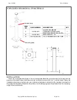
EXPLODED VIEW AND BILL OF MATERIALS
INSTALLATION
There are 4 elongated bolt holes in the mounting plate. Mark the ground surface (concrete) with the
positions of the bolts holes. Drill holes into the concrete to receive four (4)
1
/
2
” anchor bolts. Follow the
installation directions provided with your anchoring hardware to determine the diameter and depth of
the holes that should be drilled into the surface. Your building engineer should determine the necessary
length of the anchor bolts.
ITEM
NO
PART NUMBER
DESCRIPTION
QTY
1
23-524-325
GUARD WELDMENT
(CONSISTS OF BOLLARD
BODY AND MOUNTING PLATE)
1
2
23-024-483
BOLLARD CAP, 3.5
1
3
99-134-252-LBL
1”X12” RED REFLECTIVE TAPE
1
Mounting plate
Bollard body


