


37
Appendix
3
Once the front cover is removed, place it in a safe location to
prevent accidental damage. With the internal components
exposed, locate the gas inlet pipe and the gas valve near the
bottom side of the water heater.
Gas valve
Gas inlet pipe
4
Loosen the nut connecting the gas inlet pipe to the gas valve.
5
Once the gas inlet pipe is detached from the gas valve, replace
the old orifice piece and the packing with the new part for use
with LP gas. Ensure that the orifice is properly seated inside
the port.
6
Replace the gas inlet pipe to its original position and tighten
the nut to secure the gas connections.
Cascade System
When installing a cascade system, carefully consider the design of
the system and the features of the installation location. Follow all
local codes and regulations, as well as all guidelines for installing
the water heater. The following sections describe additional
considerations that are specific to installing a cascade system. Read
the following sections carefully before designing or installing the
system.
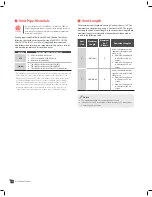
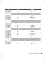
Piping sizes
When plumbing a cascade system, consider the following pipe
diameters and flow rates (note that flow rates above 6.6 ft/s may
cause pipe erosion). These specifications may vary depending on
installation conditions.
Qty
ΔT=54ºF
Flow Rate
(GPM)
Water
Velocity (ft/s)
Pipe
Diameter (mm/in)
1
6.82
4.53
20A
3/4"
2
13.64
5.32
25A
1"
3
20.46
5.25
30A
11/4"
4
27.28
4.94
40A
11/2"
5
34.10
6.19
40A
11/2"
6
40.92
4.26
50A
2"
7
47.74
4.97
50A
2"
8
54.56
5.69
50A
2"
Содержание VH-150
Страница 46: ...Memo ...
Страница 47: ...Memo ...


