background image


Vertiv


|


NetSure -48V DC Bulk Output Power System Installation and User Instructions (UM582127100)


|


Rev. E 

15 

4.


Secure the rectifier module mounting shelf to the relay rack.  Torque all screws to 65 in-lbs. 

Hardware build-up is: 
  

12-24 x 3/4" screw and flat washer, 


(1) set per side. 


12-24 x 3/4" screw and ground washer, 


(1) set per side. 

5.


Repeat for any additional rectifier module mounting shelf.  Rectifier module mounting shelves are install 
directly below each other with no space between them.  The main shelf (the one with the NCU 
Controller) should be the top-most shelf. 


Interconnecting the Rectifier Module Mounting Shelves Output Busbars in Multiple Shelf Systems 


NOTE!  

Refer to 

Figure 3

 as this procedure is performed. 


Procedure 

1.


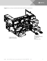
The mating busbars are factory installed on the expansion rectifier module mounting shelf.  Secure 
these busbars to the output busbars on the shelf above it.  Hardware is provided with the expansion 
rectifier module mounting shelf. 

Hardware build-up for these connections is: 
  

1/4-20 x 7/8" Bolt, 


1/4" Belleville Lock Washer, 


1/4" Flat Washer. 

Install the Belleville lock washer so the concave side is towards the busbar.  Torque all connections to 60 
in-lbs. 


NOTE!  

Some systems may come with two shelves connected together with a common relay rack 

mounting bracket and an output busbar spanning both shelves.  Connect these shelves to other shelves 
in the same manner as described here. 

2.


Repeat this procedure for each expansion rectifier module mounting shelf. 


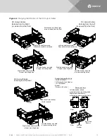
Changing the Direction of the DC Output Cables 

DC output cables can either enter from the right, from the left, or from the rear.  To reconfigure the shelf for 
these options, remove the appropriate shield and position the DC output busbars per the following procedure.  
The DC output busbars are factory connected for DC output cables entering from the right as viewed from the 
front. 

Procedure 


NOTE!  

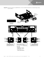
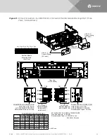
Refer to 

Figure 4

 as this procedure is performed. 


1.


I

Figure 4

, select the view for your DC output cabling requirements (left, right, or rear). 

2.


Remove the appropriate shield as required as shown in the selected view. 

Содержание NetSure 722NBBB

Страница 1: ...NetSure 48V DC Bulk Output Power System Installation and User Instructions UM582127100 Revision E Specification Number 582127100 Model Number 722NBBB ...

Страница 2: ...ble for the correct methods tools and materials to be used in performing procedures not specifically described in this document This document may contain confidential and or proprietary information of Vertiv Group Corp and its receipt or possession does not convey any right to reproduce disclose its contents or to manufacture or sell anything that it may describe Reproduction disclosure or use wit...

Страница 3: ...ptions 22 Switch Settings on IB2 Interface Board 22 Making Electrical Connections 23 Important Safety Instructions 23 Wiring Considerations 23 Relay Rack Grounding Connection Frame Ground 23 AC Input and AC Input Equipment Grounding Connections to Rectifier Module Mounting Shelves 24 Connections to 588705000 List 51 and 61 Single Phase Terminal Blocks 24 Connections to 588705000 List 52 and 62 Thr...

Страница 4: ...ler and Rectifiers 53 ESTOP Function 53 NCU Battery Charge Current Limit Feature 53 Local Controls and Indicators 53 Maintenance 54 System Maintenance Procedures 54 Adding a Rectifier Module to an Existing Rectifier Module Mounting Shelf Spec No 588705000 54 Installing a Field Expansion Rectifier Module Mounting Shelf Spec No 588705000 54 Troubleshooting and Repair 55 Contact Information 55 Contro...

Страница 5: ... injury if not avoided ANSI OSHA This admonition is not used for situations that pose a risk only to equipment data or service even if such use appears to be permitted in some of the applicable standards OSHA ALERT Alerts the reader to an action that must be avoided in order to protect equipment software data or service ISO ALERT Alerts the reader to an action that must be performed in order to pr...

Страница 6: ...hock AC input power must be completely disconnected from the branch circuits wiring used to provide power to the system before any AC electrical connections are made Follow local lockout tagout procedures to ensure upstream branch circuit breakers remain de energized during installation DO NOT apply AC input power to the system until all electrical connections have been completed and checked DC Ou...

Страница 7: ...s appropriately rated for the work to be performed Ensure that wrenches with more than one working end have only one end exposed Do not lay tools or metal parts on top of batteries Disconnect charging source prior to connecting or disconnecting battery terminals Risk of explosion if battery is replaced with an incorrect type or if polarity is reversed Recommended to replace batteries with the same...

Страница 8: ...ss Location Only authorized and properly trained personnel should be allowed to install inspect operate or maintain the equipment Do not work on LIVE parts If required to work or operate live parts obtain appropriate Energized Work Permits as required by the local authority per NFPA 70E Standard for Electrical Safety in the Workplace Hazardous Voltage DANGER HAZARD OF ELECTRICAL SHOCK More than on...

Страница 9: ...istor is necessary Read and follow wrist strap manufacturer s instructions outlining use of a specific wrist strap 3 Do not touch traces or components on equipment containing static sensitive components Handle equipment containing static sensitive components only by the edges that do not have connector pads 4 After removing equipment containing static sensitive components place the equipment only ...

Страница 10: ...Vertiv NetSure 48V DC Bulk Output Power System Installation and User Instructions UM582127100 Rev E 10 This page is intentionally blank ...

Страница 11: ...k Output Power System The NetSure 722NBBB Bulk Output Power System is intended for use to expand or replace legacy 48V DC rectifiers while retaining the distribution power board It can be used with any 48V DC power system regardless of vendor or plant type The 722NBBB is an integrated power system containing rectifiers intelligent control metering and monitoring This power system is designed to po...

Страница 12: ...and battery recharge current during normal operating conditions Refer to the Rectifier Instructions UM1R483500E for more information INSTALLATION ACCEPTANCE CHECKLIST Provided in this section is an Installation Acceptance Checklist This checklist helps ensure proper installation and initial operation of the system As the procedures presented in this document are completed check the appropriate box...

Страница 13: ...system can remain isolated from system frame and chassis DC I This system is suitable for installation as part of the Common Bonding Network CBN The installer should be familiar with the installation requirements and techniques to be used in securing the relay rack to the floor Rectifier and rectifier module mounting shelf ventilating openings must not be blocked and temperature of air entering re...

Страница 14: ...ystem was shipped on shipping rails rectifier module mounting shelves are installed in groups of two or less Space has been provided for pallet forks to fit between the sets of rectifier module mounting shelves Simply rest the pallet forks on the bottom most rectifier module mounting shelf unbolt the shelves from the shipping rails transfer the shelves to the relay rack and re secure the shelves t...

Страница 15: ...nting shelf Hardware build up for these connections is 1 4 20 x 7 8 Bolt 1 4 Belleville Lock Washer 1 4 Flat Washer Install the Belleville lock washer so the concave side is towards the busbar Torque all connections to 60 in lbs NOTE Some systems may come with two shelves connected together with a common relay rack mounting bracket and an output busbar spanning both shelves Connect these shelves t...

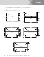
Страница 16: ...re 48V DC Bulk Output Power System Installation and User Instructions UM582127100 Rev E 16 3 Reposition the DC output lug landing busbars as shown in the selected view Figure 1 Relay Rack Floor Mounting Dimensions ...

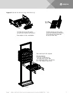
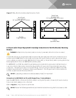
Страница 17: ...the rear center shield from each Save hardware for later re installation If multiple shelves are in the system remove and discard the bottom section of rear center shield for all shelves except the bottom shelf Rear Bottom Section Secure each shelf to the relay rack Mounting Hardware 12 24 x 3 4 Thread Forming Hex Head Screw two per side No 10 12 Ground Washer one per side No 12 Flat Washer one pe...

Страница 18: ...d User Instructions UM582127100 Rev E 18 Figure 3 Interconnecting the Rectifier Module Mounting Shelves Output Busbars Rear Components removed in illustration for clarity only 1 4 20 x 7 8 Bolt 1 4 Belleville Lock Washer 1 4 Flat Washer Busbar Torque to 60 in lbs ...

Страница 19: ...ar Reference Views Left side busbar shown mounted in lower mounting holes Right side busbar shown mounted in upper mounting holes Left Side Busbar Right Side Busbar Right side shield removed Rear bottom shield not shown Right side busbar mounted in lower mounting holes Left side busbar mounted in upper mounting holes Left side shield removed Rear bottom shield not shown References to left and righ...

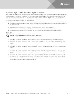
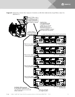
Страница 20: ...nector of a shelf plugs into the top connector on the shelf below it The bottom connector on the bottom most shelf must be terminated with a termination plug Procedure NOTE Refer to Figure 5 as this procedure is performed 1 Connect the bottom connector on the main shelf to the top connector on the 1st expansion shelf 2 Connect the bottom connector on the 1st expansion shelf to the top connector on...

Страница 21: ...oller area on main shelf Alarm Control Connections Between Shelves and Controller These two connectors are plugged together Rear View Main Shelf List 61 shown Rear View expansion shelf List 51 shown Rear View expansion shelf List 51 shown Rear View expansion shelf List 51 shown Rear View expansion shelf List 51 shown These two connectors are plugged together These two connectors are plugged togeth...

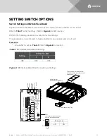
Страница 22: ... IB2 Interface Board Switch Settings Setting DIP Switch SW1 1 2 IB2 OFF OFF Figure 6 IB2 Interface Board Switch Location and Settings J12 RELAY SW1 7 J2 J11 5 3 1 Relay Output Terminal Blocks Digital Input Terminal Blocks J9 J8 J7 J6 J5 J4 J3 8 6 4 2 8 7 6 5 4 3 2 1 IB2 Board Top View NO C NC NO C NC NO C NC NO C NC NO C NC NO C NC NO C NC NO C NC 5 3 1 4 6 2 5 3 1 4 6 2 5 3 1 4 6 2 5 3 1 4 6 2 5 ...

Страница 23: ...705000 Lugs should be crimped per lug manufacturer s specifications Relay Rack Grounding Connection Frame Ground For relay rack grounding requirements refer to the current edition of the American National Standards Institute ANSI approved National Fire Protection Association s NFPA National Electrical Code NEC applicable local codes and your specific site requirements A customer s grounding networ...

Страница 24: ...e feed and rear covers rear feed of the rectifier module mounting shelf for AC input and AC input equipment grounding conductors The openings accept 1 inch conduit fittings AC input wiring should be provided to all rectifier module mounting positions including currently unused positions This wiring will ease future installation of rectifiers to meet increased load requirements NOTE A grounding con...

Страница 25: ... from the front Note that in the main shelf the 6th position is occupied by the NCU Controller 1 Make AC input connections as shown in Figure 8 Connect each wire by inserting the stripped end into the wire opening and then tightening the screw Torque connections to value shown in Figure 8 Making AC Equipment Grounding Connections NOTE Make equipment grounding connections to earth ground not to the...

Страница 26: ...z SINGLE PHASE Wire Size Capacity 6 14 AWG Recommended Torque 6 AWG 45 in lbs 8 14 AWG 35 in lbs Service Type a Line to Line Connect Line 1 to Terminal 1 Connect Line 2 to Terminal 2 b Line to Neutral Connect Line to Terminal 1 Connect Neutral to Terminal 2 TB2 TB1 TB4 TB3 1 2 1 2 1 2 2 1 2 1 2 1 Rectifier Module 1 Rectifier Module 2 Rectifier Module 3 Rectifier Module 4 Rectifier Module 6 Rectifi...

Страница 27: ...into the shelf through the previously installed conduit fittings Making AC Input Connections NOTE In each shelf rectifier module mounting positions are numbered 1 6 from left to right as viewed from the front Note that in the main shelf the 6th position is occupied by the NCU Controller 1 Make AC input connections as shown in Figure 9 Connect each wire by inserting the stripped end into the wire o...

Страница 28: ...ONNECTIONS WITHIN THE SHELF TB1 Terminal TB2 Terminal Mounting Position 1 ØA 2 ØB 3 ØC 1 ØA 2 ØB 3 ØC L1 L2 L1 L2 L1 L2 L1 L2 L1 L2 Rect 6 Rect 5 Rect 4 Rect 3 Rect 2 Rect 1 L1 L2 List 52 only ØA TB2 TB1 ØB ØC ØA ØB ØC AC IN Feed 2 Rectifier Modules 4 6 List 52 4 5 List 62 AC IN Feed 1 Rectifier Modules 1 3 List 52 62 FRAME GROUND CONNECTION ONE 10 32 X 3 4 STUD AND HARDWARE PER SIDE Recommended t...

Страница 29: ...ly wired AC outlet or distribution box Refer to Figure 10 Figure 10 AC Input Connections to a 588705000 List 53 and 63 Rectifier Module Mounting Shelf Single Phase Line Cords List 53 List 63 Rear View Rear View Rectifier Module 1 Rectifier Module 3 Rectifier Module 2 Rectifier Module 6 Rectifier Module 5 Rectifier Module 4 Rectifier Module 5 Rectifier Module 4 Rectifier Module 1 Rectifier Module 3...

Страница 30: ...n Points Locations Refer to Figure 11 Figure 11 External Alarm Reference Monitoring and Control Connection Points Locations NCU Controller NCU Controller NCU 10 100M Ethernet Port RJ 45 IB2 Controller Interface Board Sliding Tray System Interface Circuit Cards Customer Connection Terminal Block Front Top cover can be removed from controller section to facilitate circuit card access Main Rectifier ...

Страница 31: ...Table 2 Two 2 External Battery Fuse Alarm Inputs Four 4 External Load Fuse Alarm Inputs One 1 Load Shunt Input One 1 Battery Shunt Input One 1 LVD Driver Output One 1 LVD Sense Input RS 485 Port Battery Fuse Alarm Input Rating Refer to the following a The default is 400mV Anything greater than 400mV causes alarm to be raised Load Fuse Alarm Input Signal Refer to the following a Anything greater th...

Страница 32: ...by removing the top cover from the controller section of the shelf RS 485 Connection Pin 1 RS485 Pin 2 RS485 RS 232 Connection Pin 1 DCD232 Pin 2 RXD232 Pin 3 TXD232 Pin 4 DTR232 Pin 5 CGND Pin 7 RTS232 RS 232 RS 485 SYSTEM TEMP PROBE 1 SYSTEM TEMP PROBE 2 1 5 6 9 2 1 1 2 1 2 1 2 1 2 1 2 STD Controller Section of Main Shelf components removed for clarity only Factory Connected to TB5 Internal Syst...

Страница 33: ...e Battery 2 Shunt 4 Load Fuse Alarm 6 not available Load Shunt 5 Load Fuse Alarm 7 not available Load Shunt 6 Load Fuse Alarm 8 not available LVD2 Sense 7 Load Fuse Alarm 9 not available LVD2 Drive 8 Load Fuse Alarm 10 not available SPD not available STD System Internal Interface Circuit Card LVD2 Drive 9 Signal TB5 SPD not available Battery 1 Shunt not available LVD2 Sense 10 LVD1 Drive not avail...

Страница 34: ...o the following a Maximum Voltage Rating 60V DC b Active High 19V DC c Active Low 1V DC The digital inputs may be preprogrammed for specific functions Refer to the configuration drawing C drawing supplied with your system for your system s specific configuration Programmable Relay Outputs The IB2 provides eight 8 programmable alarm relays with dry Form C contacts Connect up to eight 8 relay output...

Страница 35: ...be extended when an optimum charge voltage to the battery with respect to temperature is maintained A temperature probe set to monitor battery temperature can also be used for the BTRM Battery Thermal Runaway Management feature The BTRM feature lowers output voltage when a high temperature condition exists to control against battery thermal runaway The temperature sensor end of the probe contains ...

Страница 36: ...2 5 3 1 4 6 2 5 3 1 4 6 2 5 3 1 4 6 2 Connector to controller IB2 TEMP PROBRE 1 IB2 TEMP PROBE 2 The relay assigned to Critical Summary alarm relay 1 by default will operate in the Fail Safe Mode Fail Safe Mode means Relay 1 is de energized during an alarm condition opening the contacts between the C and NO terminals and closing the contacts between the C and NC terminals The remaining seven 7 rel...

Страница 37: ...ages IB2 Pin No Factory Wiring Ground J5 5 can be connected to the other side of a customer furnished ESTOP switch 48VDC J5 6 48VDC is factory supplied to J5 6 J5 6 is also factory jumpered to J5 3 Digital Input 8 minus NOTE 48VDC is factory supplied to J5 6 which is also factory jumpered to J5 3 Digital Input 8 minus A customer provided ESTOP switch can be connected to J5 4 Digital Input 8 positi...

Страница 38: ... J6 1 2 NO J6 6 COM J6 4 NC J6 2 3 NO J7 5 COM J7 3 NC J7 1 4 NO J7 6 COM J7 4 NC J7 2 5 NO J8 5 COM J8 3 NC J8 1 6 NO J8 6 COM J8 4 NC J8 2 7 NO J9 5 COM J9 3 NC J9 1 8 NO J9 6 COM J9 4 NC J9 2 NOTE The relay assigned to Critical Summary alarm relay 1 by default will operate in the Fail Safe Mode Fail Safe Mode means Relay 1 is de energized during an alarm condition opening the contacts between t...

Страница 39: ... cable pinouts and wire colors Refer also to the external device s or system s instruction manual Procedure 1 Remove the CAN termination plug from the Controller CAN Port see Figure 5 and Figure 12 for location Connect the device or system to the Controller CAN Port using cable P N 556238 Refer to Table 5 for cable pinouts and wire colors Note that you may have to cut the end off of the cable if i...

Страница 40: ...ble connected directly between your PC and the NCU Controller WARNING The intra building port s of the equipment or subassembly is suitable for connection to intra building or unexposed wiring or cabling only The intra building port s of the equipment or subassembly MUST NOT be metallically connected to the interfaces that connect to the OSP or its wiring These interfaces are designed for use as i...

Страница 41: ...rovide 3 8 clearance holes for installation of customer provided two hole lugs that have 1 inch centers and 3 8 inch bolt clearance holes Customer must order or provide lug mounting hardware You connect DC output leads per a single rectifier shelf in the system or for pairs of rectifier shelves in the system depending on how many shelves are in the system Refer to Figure 14 DC output cables can ei...

Страница 42: ...n per two shelves bottom 1 connection per two shelves top 1 connection per single shelf bottom 1 connection per two shelves top 1 connection per two shelves middle 1 connection per single shelf bottom 1 connection per single shelf 4 Shelf System 5 Shelf System 48V DC OUTPUT CONNECTIONS 3 8 Clearance Holes on 1 Centers Customer must order or supply ug mounting hardware Maximum Lug Width 1 31 for th...

Страница 43: ...ulk Output Power System Installation and User Instructions UM582127100 Rev E 43 Figure 15 Typical Lug Layout Diagrams Three 3 Lugs Layout Diagram Maximum Lug Tab Width 1 31 Two 2 Lugs Layout Diagram Maximum Lug Tab Width 1 78 ...

Страница 44: ... modules on the left hand side of the shelf The second three phase input feeds the two List 62 or three List 52 rectifier modules on the right hand side To maintain phase balance install rectifier modules in groups of three List 52 that is fill all three mounting positions on the left and or all three on the right To maintain phase balance install rectifier modules in groups of two or three List 6...

Страница 45: ...ve been checked Ensure that rectifier module mounting positions are filled by a rectifier module or a blank cover panel as desired It is acceptable for positions to be left vacant Refer to the configuration drawing C drawing supplied with your power system documentation for factory settings of adjustable parameters Initially Starting the System Procedure 1 Apply DC input power to the system by clo...

Страница 46: ...le alarm can be silenced at any time by momentarily depressing the ENT key on the NCU Controller 1 After the NCU is powered on the display shows the logo screen The controller is initializing 2 When initialization is complete the language screen appears Press the up or down arrow key to select the desired language Press the ENT key to confirm the selection 3 The Main Menu displays See Figure 18 St...

Страница 47: ...n Menu press the UP and DOWN keys to highlight the desired Menu graphic in the Main Menu Press the ENT key to enter the selected menu NOTE Repeatedly press the ESC key to return in reverse order level by level from any submenu until the Main Menu appears 6 Verify and set the NCU controller as required for your application Refer to the NCU Instructions UM1M830BNA for procedures Note that you will h...

Страница 48: ...ction in the NCU Instructions UM1M830BNA Verifying the Configuration File Your NCU was programmed with a configuration file that sets all adjustable parameters The version number of the configuration file can be found on the configuration drawing C drawing that is supplied with your power system documentation and on a label located on the NCU You can verify that the correct configuration file has ...

Страница 49: ...e 7 NCU Basic Settings Menu Navigation Parameter Menu Navigation Date Main Menu Settings Icon Sys Settings Date Time Main Menu Settings Icon Sys Settings Time IP Communications Parameters IP address subnet mask address gateway address Main Menu Settings Icon Comm Settings enter parameters Float Voltage Main Menu Settings Icon Batt Settings Charge Float Voltage Equalize Voltage Main Menu Settings I...

Страница 50: ...fies the rectifiers is by serial number lowest serial number is Rect 1 next lowest is Rect 2 etc If you prefer the NCU to identify the rectifiers by position in the system perform the following procedure Upon power up the NCU arbitrarily assigns Feed AC1 AC2 or AC3 to each rectifier This assignment is used to display rectifier AC input feed voltage s The User may reassign the feed to each rectifie...

Страница 51: ...us of the indicators located on the controller and rectifiers If the system is operating normally the status of these is as shown in Table 8 Table 8 Status and Alarm Indicators Component Indicator Normal State NCU Status Green On Minor Yellow Off Critical or Major Alarm Red Off Rectifier Modules or Power Green On or Protection Yellow Off or Alarm Red Off ...

Страница 52: ...ate NOTE Note that provided on a USB drive furnished with the system is a controller configuration drawing C drawing and the controller configuration files loaded into the controller as shipped 2 Close the distribution cabinet s front door and turn the latch clockwise to secure the door system s in a relay rack or close the system s enclosure door 3 Verify all rectifier modules and the controller ...

Страница 53: ...en some battery cells are permanently damaged the current to the batteries can be quite extensive To avoid overheating or further damages to the battery the NCU can be programmed to limit the battery current to a preset level by limiting the charging voltage of the rectifiers Should the battery current still exceed a higher preset value an alarm is issued The controller limits the current going to...

Страница 54: ... a rectifier module can easily be added to an existing rectifier module mounting shelf Spec No 588705000 that contains an empty rectifier module mounting position It is recommended that the current limit point be checked whenever a rectifier module is added to or removed from the power system Refer to Checking the NCU Current Limit Point after Adding or Removing a Rectifier on page 55 The rectifie...

Страница 55: ... to clear the alarm Replacement Information on page 56 and Replacement Procedures on page 56 Troubleshooting Alarm Conditions on the NCU Controller The NCU Controller displays alarm conditions as listed in the Resolving Alarms section of the NCU Instructions UM1M830BNA Programmable external alarm relays are also available Refer to Digital Inputs and Programmable Relay Outputs on page 34 and the co...

Страница 56: ...ectifier module replacement procedure Refer also to System Troubleshooting Information on page 55 The rectifier module being replaced is assigned by the NCU the lowest available identification number If desired you can change the identification number See Configuring the NCU Identification of Rectifiers and Assigning which Input Feed is Connected to the Rectifiers on page 50 Replacing the NCU Cont...

Страница 57: ...m the customer connection terminal blocks DO NOT allow the bare wire end to contact any grounded or energized object Isolate the wire end with electrical tape Repeat for each wire to be removed 8 Unplug all connectors plugged into the circuit card 9 Remove the remaining circuit card mounting screws and remove the circuit card from the mounting plate 10 In this step ensure you do not intermix the o...

Страница 58: ...oller Interface Board assembly completely into the main rectifier module mounting shelf and secure with the captive fastener 16 Remove the grounding wrist strap 17 Enable the external alarms or notify appropriate personnel that this procedure is finished 18 Ensure that there are no local or remote alarms active on the system ...

Страница 59: ...8 J7 J6 J5 J4 J3 8 6 4 2 8 7 6 5 4 3 2 1 IB2 Board Top View NO C NC NO C NC NO C NC NO C NC NO C NC NO C NC NO C NC NO C NC 5 3 1 4 6 2 5 3 1 4 6 2 5 3 1 4 6 2 5 3 1 4 6 2 5 3 1 4 6 2 5 3 1 4 6 2 5 3 1 4 6 2 Connector to controller IB2 TEMP PROBE 1 IB2 TEMP PROBE 2 Main Rectifier Module Mounting Shelf Top cover can be removed from controller section to facilitate replacement IB2 Board Sliding Tray...

Страница 60: ...Vertiv com Vertiv Headquarters 1050 Dearborn Drive Columbus OH 43085 USA UM582127100 RE 08 19 ...

Отзывы: