


Vertiv™ NetSure™ -48 VDC GMT Distribution Unit Installation and User Manual
Proprietary and Confidential © 2022 Vertiv Group Corp.
9
5.7
Input Wiring
WARNING!
Observe proper polarity when making input connections.
Input source and input return leads terminated in two-hole lugs are connected to threaded studs located on the rear inside of the
distribution unit (refer to
). Refer to
also for stud size/spacing and recommended torque.
Input wire size and lug requirements vary depending on power requirements, therefore no specific information is provided for wire
size. Refer to
for recommended wire sizes and lugs at rated maximum assembly load and other various loads. Note that
loads typically should not exceed 80% of capacity; therefore, input wires have been sized for an overcurrent protection device rated at
125% of the expected load. All lugs for customer connections must be ordered separately. See
for available lugs.
NOTE!
The DC return connection to this system can remain isolated from system frame and chassis (DC-I).
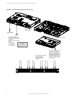
Using Side Access Holes
Optional 19” mounting brackets P/N SXA2300282 can be installed to allow wiring through the side access holes in the shelf. Requires
5” front projection mounting.
Procedure
1.
Install mounting brackets P/N SXA2300282.
2.
Remove the top cover.
3.
Select which side of shelf you want to bring the wires in from. Install supplied bushing into the access hole on this side.
Install plug into the access hole on the other side. Refer to
4.
Run customer supplied wires from RTN and -48 VDC studs in the shelf through the access hole to the appropriate external
terminations.
5.
Replace the top.
6.
Wire the shelf’s FA termination to the external alarm circuits as required.
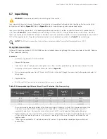
Table 5.1
Recommended Input External Branch Circuit Protection, Wire Sizes, and Lug
External Overcurrent Protection
Device Rating
Ambient
Operating
Temperature
(1)
Loop
Length (Ft)
1.0 Voltage
Drop
(2)
Recm 90
°
C
Wire Size
(AWG)
(1)
Recommended
Crimp Lug
(3)
150 A
40°C
63
1/0
112902
125 A
40°C
76
1/0
112902
100 A
40°C
59
2
245346900
1
Wire sizes based on recommendations of the American National Standards Institute (ANSI) approved National Fire
Protection Association's (NFPA) National Electrical Code (NEC). Table 310.15 (B) (16) for copper wire at 90 °C
conductor temperature. For operation in countries where the NEC is not recognized, follow applicable codes.
2
Recommended wire sizes are sufficient to restrict maximum voltage drop to 1.0 volt at rated full load output current
of the shelf for the loop lengths shown in this column. Loop length is the sum of the lengths of the positive and
negative leads.
3
These lugs are two-hole for 1/4” bolt clearance on 5/8” centers. Lugs should be crimped per lug manufacturer’s
specifications.