Vertiv™ |
Liebert® EXM™ UPS 20-100kVA, 50/60Hz User Manual |
20
3.2.5
Cabling Guidelines
The following are guidelines only and are superseded by local regulations and codes of practice where
applicable. Use wiring rated at 75°C or greater.
•
Take special care when determining the size of the neutral cable, as current circulating on the neutral cable may be greater
than nominal current in the case of non-linear loads. Refer to the values in
7.3 - UPS Electrical Characteristics
.
•
The ground conductor should be sized according to such factors as the fault rating, cable lengths and type of protection. The
ground cable connecting the UPS to the main ground system must follow the most direct route possible. Control wiring and
power wiring must be run in separate conduit. Output and input cables must be run in separate conduit.
•
Consider using paralleled smaller cables for heavy currents—this can ease installation.
•
Refer to SL-25651 for guidelines and instructions when sizing battery cables.
•
In most installations, the load equipment is connected to a distribution network of individually protected busbars fed by the
UPS output, rather than connected directly to the UPS itself. When this is the case, the UPS output cables can be rated to suit
the individual distribution network demands rather than being fully load-rated.
•
When laying power cables, do not form coils; this will help avoid increasing formation of electromagnetic interference.
3.2.6
Cable Connections
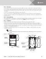
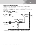
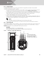
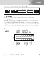
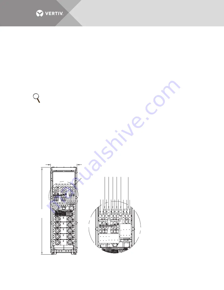
The rectifier input, bypass, output and battery are easily accessible from the front of the unit for installation. All
require lug type terminations. They are connected to busbars on the front of the Liebert
®
EXM, as shown in
. These busbars are accessible when the I/O panel is removed.
NOTICE
Risk of improper installation. Can cause equipment damage.
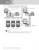
When wiring a single-input only system, connect only the power wiring to the input busbars.
Figure 9
Input busbars—Liebert
®
EXM 20-100kVA frame
NOTE
If more load is added to the distribution panel, the unit’s cabling must be resized.
Rectifier Input
A
Bypass Input
A
Bypass Input B
Bypass Input C
Output Neutral
Output A
Output B
Output C
Ground
Rectifier Input B
Rectifier Input C
Batt - N
Batt +
Batt -
Input Neutral
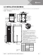
78.56"
(1994mm)
23.6" (600mm)
See
Detail A
FRONT VIEW
Door Removed
DETAIL A
NOTES
1. Control wiring and power wiring
must be run in separate conduits.
3. Shown with seismic mounting bracket.
4. All wiring must be in accordance
with national and local electrical codes.
Содержание Liebert EXM
Страница 1: ...Liebert EXM UPS User Manual 20kVA to 100kVA 208 120V 50 60Hz...
Страница 77: ......


