Vertiv™ XTE 802G Generator Room Walk-In-Cabinet Description and Installation Manual
51
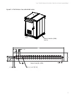
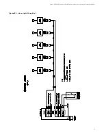
Figure 9-5:
Combo Site Grounding Scheme (Concrete / On the Ground Platform Foundation)
Grounding
Conductor
Size
Minimum Bending Radius (inches)
(Insulated RHH/RHW)
Solid
(Uninsulated)
Recommended
Required
6 AWG
12
2
1-1/2
4 AWG
12
3
na
2 AWG
12
3
2
1/0 AWG
12
4
na
4/0 AWG
12
4
na
750 kcmil
12
7
na
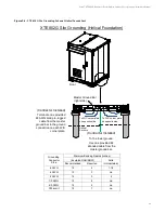
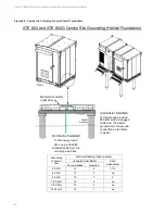
XTE 802 and XTE 802G Combo Site Grounding
(Concrete / On the Ground Platform Foundation)
To the ground ring.
(Contractor Installed)
(Contractor Installed)
To the tower ground.
Use second provided #2
stranded cable from the
master ground bar.
Use one provided #2
stranded cable from the
master ground bar.
(Contractor Installed)
Terminate one provided
#2 AWG solid pre-lugged
cable from the master
ground bar to the ground
connection on the frame
or beam.
Master Ground Bar
(right side)
Front


