Vertiv ES-HND200I-EI Скачать руководство пользователя страница 7

4

Vertiv

 | Network Camera Quick Operation Guide | v01 | UD.6L0201D0140A02

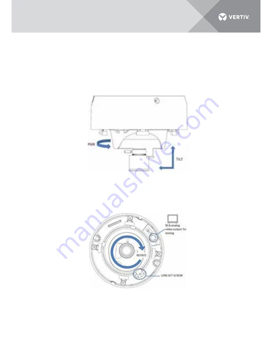
3.)    Connect the RCA analog video output with a monitor to view the image of the camera. Loosen the lens set    
        screw and pan, tilt or rotate the lens to get a desired surveillance angle. Adjust the lens focus to obtain a perfect      
        image. Fasten the lens set screw.

Figure 2-4 Image Adjusting

Figure 2-5 Image Adjusting

Содержание ES-HND200I-EI

Страница 1: ...Network Camera V4 1 0 ES HND200I EI Installer User Guide ...

Страница 2: ...1 0 Appearance Description 1 1 1 Camera Description 1 1 1 2 Camera Wiring Diagram 1 2 0 Installation 2 2 1 Ceiling Moungting 2 2 2 In Ceiling Moungting 5 3 0 Setting the Network Camera over the LAN 9 3 1 Modify device info 10 4 0 Accessing via Web Browser 12 CONTENTS ...

Страница 3: ... UL has only tested for fire shock or casualty hazards as outlined in UL s Standard s for Safety UL60950 1 UL Certification does not cover the performance or reliability of the security or signaling aspects of this product UL MAKES NO REPRESENTATIONS WARRANTIES OR CERTIFICATIONS WHATSOEVER REGARDING THE PERFORMANCE OR RELIABILITY OF ANY SECURITY OR SIGNALING RELATED FUNCTIONS OF THIS PRODUCT Save ...

Страница 4: ...utton 3 AUDIO OUT Audio output interface 4 MIC IN Audio input interface 5 D D RS 485 interface 6 1A 1B 2A 2B Alarm output interface 7 IN1 GND IN2 GND Alarm input inter face 8 Power supply interface 1 1 2 Camera Wiring Diagram 1 1 1 Overview Note After the powering on of the camera pressing and holding the INITIAL SET button for about 10 seconds can reset all the parameters to the default settings ...

Страница 5: ...good ventilation is required for a proper operating environment You may refer to the specification of the product for the detailed information about installation environment If the product does not function properly please contact your dealer or the nearest service center Do not disassemble the camera for repair or maintenance by yourself 2 1 Ceiling mounting NOTE If required you can use a plier t...

Страница 6: ...e screws to fix the mounting base to the ceiling rotate the back box counterclockwise to secure it to the mounting base use the lock screw to secure the dome camera 2 Loosen the set screws with the hex key supplied to remove the lower dome Figure 2 2 Mounting Figure 2 3 Disassembling ...

Страница 7: ...analog video output with a monitor to view the image of the camera Loosen the lens set screw and pan tilt or rotate the lens to get a desired surveillance angle Adjust the lens focus to obtain a perfect image Fasten the lens set screw Figure 2 4 Image Adjusting Figure 2 5 Image Adjusting ...

Страница 8: ...peration Guide v01 UD 6L0201D0140A02 4 Reinstall the lower dome and tighten the screws Figure 2 6 Reinstall 1 Secure the mounting base to the in ceiling mounting base with screws Steps 2 2 In ceiling mounting Figure 2 7 Mounting Base ...

Страница 9: ...fix the camera Lock screw Figure 2 8 Camera and Mounting Base 3 Cut a 176 180 mm diameter hole in the ceiling and push the dome camera with in ceiling mounting base to the hole NOTE If required you can use a plier to remove one clip or both two clips marked in dotted line in Figure 2 1 on the side of the back box and then route cables through the opening to secure the cables on the ceiling Figure ...

Страница 10: ...1 UD 6L0201D0140A02 4 It is strongly recommended that you use a safety rope to secure the in ceiling mounting base to the roof 5 Fasten the lock screws to secure the dome camera Figure 2 10 Safety Rope Lock screw Lock screw Figure 2 11 Fasten Screws ...

Страница 11: ...o view the image of the camera Loosen the lens set screw and pan tilt or rotate the lens to get a desired surveillance angle Adjust the lens focus to obtain a perfect image Fasten the lens set screw Reinstall the lower dome 7 Install the trim plate with screws to finish the installation Figure 2 12 Image Adjusting Figure 2 13 Trim Plate Installing ...

Страница 12: ...ork camera in the LAN and list the device information like IP address subnet mask port number device serial number device version etc shown in Figure 3 2 y y Use iVMS 4200 software and to list the online devices Please refer to the user manual of client software for detailed information 2 Change the IP address and subnet mask to the same subnet as of your PC Refer to the following introductions to...

Страница 13: ...lumn heading to order the information you can click to show the device table and hide the network parameter panel on the right side or click to show the network parameter panel 3 1 Modify device Infor mation Steps 1 Left click to select a device to be modified in the device list as shown in Figure 3 3 The network parameters of the device will be displayed in the Modify Network Parameters panel on ...

Страница 14: ...web browser to get the liveview Notes The default IP address is 192 0 0 64 The default user name is admin and password is 12345 Use iVMS 4200 software and to list the online devices Please refer to the user manual of client software for detailed information For accessing the network camera from different subnets please set the gateway for the network camera after you log in ...

Страница 15: ...r RAM 1G or higher Display 1024 768 resolution or higher Web Browser Internet Explorer 6 0 and above version Apple Safari 5 02 and above version Mozilla Firefox 3 5 and above version and Google Chrome 8 and above version Steps 1 Open the web browser 2 In the browser address bar input the IP address of the network camera e g 192 0 0 64 and press the Enter key to enter the login interface 3 Input th...

Страница 16: ...stall the plug in before viewing the live video and managing the camera Please follow the installation prompts to install the plug in NOTE You may have to close the web browser to finish the installation of the plug in Figure 4 2 Download Plug in Figure 4 3 Download Plug in ...

Страница 17: ...A02 Figure 4 4 Install Plug in Figure 4 5 Install Plug in 6 Reopen the web browser after the installation of the plug in and repeat the above steps 2 4 to login NOTE For detailed instructions of further configuration please refer to the user manual of network camera ...

Страница 18: ...referred to are trade names trademarks or registered trademarks of their respective owners While every precaution has been taken to ensure accuracy and completeness herein Vertiv Co assumes no responsibility and disclaims all liability for damages resulting from use of this information or for any errors or omissions Specifications are subject to change without notice ...

Отзывы: