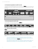
4.1.2 Maximum Steady State AC and DC Currents
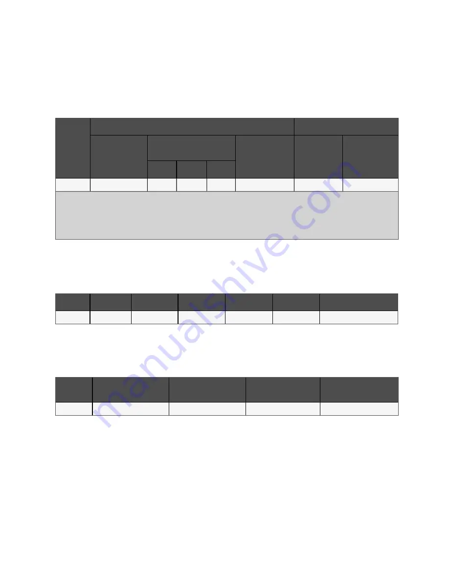
The power cable must be selected according to the current and voltage values in Table 4.1 below as well as the local wiring
regulations, and take environmental conditions (temperature and physical media) into consideration, then refer to Table 3B
in IEC 60950-1.
U PS
p ower
(kV A )
Rated current (A )
Bus s tud b olt/nut s p ecification
M ax. inp ut
current
1,2
O utp ut/b yp as s current
2
at full
load
Battery d is charg e
3
current (+, - , N ) at
m in. b attery voltag e
Inp ut, b attery,
outp ut,
b yp as s /PE
cab le
Recom m end ed
torq ue (N m )
380 V
4 0 0 V
4 15 V
250 kVA
496
380
363
348
903
M12
39 ± 10%
Note:
1. Max. current of low voltage (176 V) for rectifier input at full load.
2. Non-linear load (like switch power) affects the design of output and bypass neutral line.
3. The discharge current at EOD point (voltage is 9.6 V) calculated by 30-block battery.
T able 4.1 M ax. steady state A C an d DC cu rren ts
4.1.3 Recommended CSA of UPS Cable
The recommended CSA of the single module cable is listed in Table 4.2 below.
M od el
Inp ut
O utp ut
Byp as s
N eutral line
E arth cab le
Battery
250 kVA
2*95
2*70
2*70
2*95
95
See
T able 4.2 R eco m m en ded CSA o f th e UP S sin gle m o du le cable (u n it: m m
2
, am bien t tem peratu re: 25 °C)
4.1.4 Selection of UPS I/O Switch
Table 4.3 below shows inbuilt switch assembly capacities.
M od el
Rectifier inp ut s witch
(op tional)
Byp as s inp ut s witch
(op tional)
O utp ut s witch (op tional)
M aintenance b yp as s s witch
(s tand ard )
80 kVA
500 A (3P), isolating switch
500 A (3P), isolation switch
400 A (4P), isolating switch
400 A (3P), isolating switch
T able 4.3 In bu ilt UP S I/O switch capacity
N O T E:
1. T h e switch o f UP S m o du le is an iso latio n switch by defau lt. T o preven t UP S fau lt fro m
spreadin g to th e u pstream o f cu sto m ers, it is reco m m en ded to in pu t a separate switch to th e
UP S acco rdin g to th e cu rren t valu e in
.
2. W e reco m m en d co n figu rin g Vertiv B CB bo x fo r th e UP S with extern al batteries. If B CB is n o t
selected, please select battery switch acco rdin g to B CB param eters sh o wn in 9.5 B CB B o x.
4 Electrical Installation
34
Vertiv™ Liebert® APM Plus User Manual
Содержание APM 0250kMK16FN02000
Страница 1: ...Vertiv Liebert APM Plus User Manual 50 250 kVA UPS...
Страница 8: ...vi This page intentionally left blank Vertiv Liebert APM Plus User Manual...
Страница 16: ...1 Important Safety Instructions 8 This page intentionally left blank Vertiv Liebert APM Plus User Manual...
Страница 30: ...2 Overview 22 This page intentionally left blank Vertiv Liebert APM Plus User Manual...
Страница 60: ...4 Electrical Installation 52 This page intentionally left blank Vertiv Liebert APM Plus User Manual...
Страница 73: ...Figure 5 11 Customize the display 5 Operator Control and Display Panel 65 Vertiv Liebert APM Plus User Manual...
Страница 97: ...5 Operator Control and Display Panel 89 Vertiv Liebert APM Plus User Manual...
Страница 154: ...Figure 8 8 LBS port J4 on bypass control module 8 Parallel System and LBS System 146 Vertiv Liebert APM Plus User Manual...
Страница 182: ...11 Service and Maintenance 174 This page intentionally left blank Vertiv Liebert APM Plus User Manual...
Страница 188: ...12 Specifications 180 This page intentionally left blank Vertiv Liebert APM Plus User Manual...
Страница 191: ...Vertiv Liebert APM Plus User Manual...

