background image

Controller Operation

33

To acknowledge alarms
1. On the ALARMS panel, press Acknowledge All: A check mark overlays the status indicator of the active alarms and 

warnings, and these automatically clears when the condition is no longer present.
2. If a critical event must be reset manually, then the acknowledged items are listed with a Reset All button on the ALARMS 

panel.
3. Touch Reset All to manually reset the condition.

Table 6-5 Events that Clear without Acknowledgment

Network Failure

Description

Unit xx disconnected

The iCOM I/ O board assigned as U2U address number XX (two up to thirty- two) has lost 

communication with the group

Make sure all units are powered-on at the disconnect

Check cable connections and network setting wherever applicable

No connection W/unit 1

The iCOM I/O board assigned as U2U address number 1 has lost communication with the group

Make sure all units are powered-on at the disconnect

Check cable connections and network setting wherever applicable

BMS disconnect

The BMS/BAS has not completed a handshake within the time defined by the BMS/ BAS

Verify monitoring connection and communication to the BMS/ BAS panel

Unit code missing

The Factory unit code must be confirmed, saved and executed

Unit code mismatch

The Factory unit code must be confirmed, saved and executed

Ambient sensor failure

The outdoor temperature/humidity sensor used on the air economizer unit has become 

disconnected or is no longer working properly

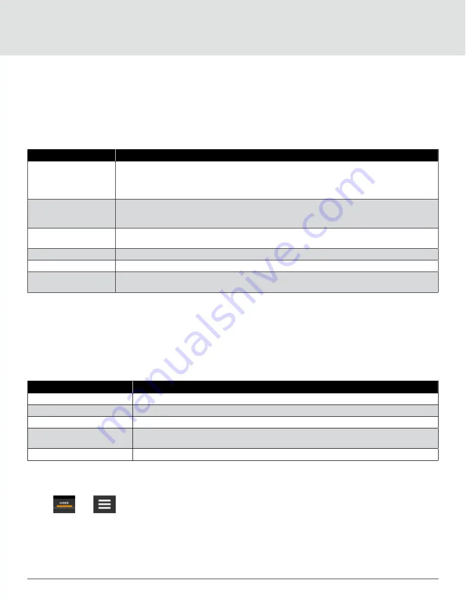
6.5.6. Viewing the Event Log

The event log is a list by date/ time of the last 400 events generated by iCOM for the thermal-management unit. On the User 

menu, press Event Log. The EVENT LOG for the cooling unit opens. 

Table 6-6

 describes the color-coded status for each 

event.

Note: Depending on the type of thermal management unit, included components and control settings of your system, the 

options on your iCOM display may differ.

Table 6-6 Events that Clear without Acknowledgment

Indicator

Description

Green Dot

Message

Yellow Dot

Unacknowledged warning event. See acknowledge alarm on the previous page

Red Dot

Unacknowledged alarm event. See acknowledge alarm on the previous page

White Dot with Check-mark 

overlay

Acknowledged event, the cause still exists

White circle

Acknowledged event, the cause is cleared

6.5.7. Viewing Sensor Data

The Sensor Data panel lists the standard and optional sensors monitored by iCOM and the current readings of each sensor.

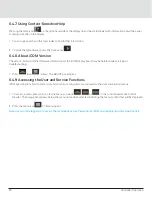
1. Press 

 then 

 > Sensor Data. The Sensor Data panel opens.

2. A secondary panel displays the DAILY SENSOR READING SUMMARY, which shows temperature, humidity and dew-point 

readings for the cooling unit.

Содержание 01307092

Страница 1: ...Liebert AHU Precision Air Conditioning Technical Manual ...

Страница 2: ... the purchasing scope or the usage scope Unless otherwise specified in the contract all statements information and recommendations in this document are provided AS IS without warranties guarantees or representations of any kind either express or implied The information in this document is subject to change without notice Every effort has been made in the preparation of this document to ensure the ...

Страница 3: ...le Situation Description Warning Danger Caution The Warning Danger Caution note indicates a hazardous or potentially harmful situation that can result in death or injury It also indicates instructions that need to be adhered to failing which may result in danger and safety issues thereby having an adverse effect on the reliability of the device and security Even for practices not related to physic...

Страница 4: ...prior to installing or operating the system Disconnect the local and remote power supplies prior to working with the unit Prior to the installation process read all the instructions verify if all the parts are in place and check the nameplate to ensure the voltage matches the available utility power for the unit The controller doesn t isolate power from the unit even in the Off mode and some inter...

Страница 5: ... 2 Storage Environment Requirements 4 3 Technical Parameter 5 3 1 Performance Parameters 5 3 2 Product Dimensions 6 3 2 1 Overall Dimensions 6 3 2 2 Position and Dimension of Steel Base 8 3 2 3 Position and Dimension of Top Cover 8 3 2 4 Position and Dimensions of Supply Air Side 10 3 2 5 Position and Dimension of Air Inlet 10 4 Components Features 11 4 1 Components 11 4 1 1 EC Fan 11 4 1 2 Coil 1...

Страница 6: ...Air Pressure Sensor 14 4 2 3 Airflow Meter 14 4 2 4 Power Meter 14 4 2 5 PICV 14 4 2 6 Smoke Detector 14 4 2 7 Ultracap 14 5 Product Handling and Installation 15 5 1 Unit Unloading 15 5 2 Installing Floor Stand 15 5 3 Upper Cabinet Hoisting 17 5 4 Unit Connection And Wiring 19 5 5 Maintenance Space Requirements 21 6 Controller Operation 22 6 1 Touchscreen Display and User Interface 22 6 2 Touchscr...

Страница 7: ... 6 4 9 Accessing the User and Service Functions 29 6 4 10 User Menu 30 6 4 11 Service Menu 30 6 4 12 Advanced Menu 31 6 5 User Operation 32 6 5 1 Editing Humidity Setpoints 32 6 5 2 Editing Temperature Setpoints 32 6 5 3 Viewing Unit Alarms 32 6 5 4 Silencing an Audible Alarm 32 6 5 5 Acknowledging Alarms 32 6 5 6 Viewing the Event Log 33 6 5 7 Viewing Sensor Data 33 6 5 8 Managing Run Hours for a...

Страница 8: ... of precision air conditioners for data centers and large ecosystems delivering high availability and close control of the environment providing the boost for maintaining these ambient requirements With advanced remote monitoring and control software it helps to prevent possible alarm conditions and allows proactive maintenance and early detection of bottlenecks With periodic reporting the data co...

Страница 9: ...ions Digit 8 Airflow F Aluminum profile and foaming board 1 EC Fan with plastic impeller M Sheet metal 2 EC Fan with metal impeller Digit 17 Mains Switch High Voltage Option 3 PFC Fan THDi 5 1 ATS C1000 Digit 9 Power Supply 3 ATS C300 N 380 415 V 3 ph 50 60 Hz N Digit 18 Installation Option M 380 415 V 3 ph 50 60 Hz without N 0 None Digit 10 Cooling System S Vibration isolators PAD type Seismic re...

Страница 10: ... Factory Code 0 9 Factory Code 1 4 Standard Configuration The Standard configuration for Cooling module and Fan module is mentioned in the following table in Table 1 2 Table 1 2 AHU Model Nomenclature Sr No Unit Code Unit Model Module Type Remark 1 01307092 FA065HC1NE09020F1070P0000 Aluminum profile Foam board 2 01307093 FA065HC1NE09020M1070P0000 Sheet metal 3 02093790 Lifting tooling Purchase one...

Страница 11: ...um for return air temperature is 105 F 40 C and maximum dew point is 59 F 15 C Protection level cooling unit IP20 Altitude 1000 m derating is required when located altitude is above 1000 m Operation voltage range 380 415 V 3 Ph N 50 60 Hz 2 2 Storage Environment Requirements Table 2 2 Storage Environment Requirement Item Requirement General requirements Clean room no dust Environment humidity Less...

Страница 12: ...ethane Insulation Cotton Capacity Return Air T H 36 o C 26 Supply Air T H 22 o C 60 Chilled Water Temp o C 15 22 Water Flow L s 10 8 Water PD kPa 60 Cooling Capacity kW 300 Sensible Cooling Capacity kW 300 Fan Air Flow m3 h 65000 Model EBM R3G630FB3203 Quantity 4 ESP Pa 100 Power kW 13 Air Damper Dimensions mm 680 x 680 x 125 Quantity 4 Actuator Model Belimo SMQ24A Coil Type Copper Tube Aluminum F...

Страница 13: ...od Flange Flange Model DN80 PN16 Condensate Drain Gravity Drainage Drain Pipe G 1 1 4 Electrical Parameter Power Supply 380 415 V 3 ph 50 Hz 60 Hz N FLA A 22 8 Sound Power Sound Power Level dB LwA 81 3 3 2 Product Dimensions 3 2 1 Overall Dimensions The dimensions and weight of AHU are depicted in Figure 3 1 Figure 3 2 Figure 3 3 and Table 3 2 respectively Figure 3 1 AHU Outline Drawing ...

Страница 14: ... 7 Figure 3 2 Upper Section Figure 3 3 Lower Section Figure 3 4 Horizontal group installation ...

Страница 15: ...etal 2800 x 1600 x 3600 2400 2400 2800 2800 Upper Section 2800 x 1600 x 1740 2900 x 1790 x 2222 1100 1100 1400 1400 Lower Section 2800 x 1600 x 1860 2790 x 1790 x 2168 1300 1300 1400 1400 3 2 2 Position and Dimension of Steel Base The base dimensions are shown in Figure 3 5 Figure 3 5 Steel Base unit mm 3 2 3 Position and Dimension of Top Cover The position and dimension of top cover are shown in ...

Страница 16: ...e inlet DN80 4 Low voltage entrance M25 2 Water pipe outlet DN80 5 Condensate drain outlet G1 1 4 3 Incoming high voltage power supply entrance M40 Table 3 3 Dimensions of Top Cover unit mm A B C D E 285 475 285 475 170 Figure 3 7 Inlet and Outlet Pipe Flange unit mm ...

Страница 17: ...it mm 3 2 5 Position and Dimension of Air Inlet The electric box is embedded on the return air side and the electric box door of the lower cabinet is equipped with a color display emergency switch and a light switch 16 filter screens are arranged at the return air outlet The position and dimensions of air inlet are shown in Figure 3 9 respectively Figure 3 9 The Position of Air Outlet on Unit unit...

Страница 18: ...The EC Fans used in the AHU models are energy efficient and innovative with integrated electronics and maintenance free design These fans provide a cost effective way to introduce energy efficient technology by regulating the airflow and reducing the fan input power Also the easy to connect feature bundled with the benefit of minimal wiring adds to the high performance with a greater range of poss...

Страница 19: ...c coating as standard 4 1 3 EPIV EPIV Electronic Pressure Independent Valve The water flow of the unit can be controlled very accurately even if the water pressure fluctuates the water flow can be kept stable with EPIV EPIV has the characteristics of high reliability maintenance free fast response and direct flow control 4 1 4 9 inch Color Display AHU is available with 9 inch touch screen as a sta...

Страница 20: ...d with power alarm 4 1 7 Supply Air Temperature Sensor Supply Air Temperature Sensor can monitor the supply air temperature of the AHU The supply air temperature can be set on the display When the supply air temperature exceeds the set value the unit will alarm 4 1 8 Return Air Temperature Humidity Sensor Return air temperature humidity sensor can detect the return air temperature and humidity of ...

Страница 21: ...r frequency voltage current etc 4 2 5 PICV PICV Pressure Independent Control Valve The difference between PICV and EPIV is that it is mechanical rather than electronic It is also possible to accurately control the water flow while ensuring a constant flow without being affected by water pressure fluctuations 4 2 6 Smoke Detector Smoke detection system facilitates the data center to detect smoke in...

Страница 22: ...5 tons so the forklift with lifting capacity exceeding more than 3 5 tons shall be used so as to ensure the unloading safety 2 The forklift arm shall be open to the widest distance to allow it under the mounting base and ensure that the forklift arm matches with the unit in length 3 When using the forklift to move the unit move slowly to avoid damaging the unit or scratching the surface 4 When the...

Страница 23: ...uired to be very flat Therefore the customer needs to make a floor stand to meet this condition This floor stand is also conducive to the connection of the AHU condensate drain pipe so it is recommended that the height be above 100 mm Figure 5 3 is a schematic diagram of the floor stand for customers reference Figure 5 3 Schematic diagram of floor stand Lower Section Upper Section ...

Страница 24: ...termined according to the site conditions 5 3 Upper Cabinet Hoisting After the lower cabinet and the floor stand are fixed the upper cabinet needs to be hoisted on top of the lower cabinet to form a whole unit Please follow the steps below for hoisting 1 Install hoisting fixtures on the aluminum profiles in the lower part of the upper cabinet The hoisting tooling is composed of four steel frames a...

Страница 25: ...nit Figure 5 6 Wooden Base 3 Install eyelet and sling Figure 5 7 Eyelet 4 The unit needs to be protected before hoisting Pad some thick EPE or other things between the sling and the frame of the unit After completing the above steps start hoisting During the hoisting process it is necessary to ensure that the force in all directions is consistent and the unit is stable ...

Страница 26: ... is completed cabinet connection and wiring are required 1 Install the connectors of the outside panel for the unit 2 There is a plug in box in the electrical box of the upper cabinet The cables of the upper cabinet and the lower cabinet are plugged in according to the wire mark here The installation effect is as Figure 5 8 and Figure 5 9 Figure 5 8 Foam board ...

Страница 27: ...Vertiv Liebert AHU Technical Manual 20 Figure 5 9 Sheet metal ...

Страница 28: ...r environment Note3 Avoid positioning the indoor unit in concave or narrow areas which can baffle the airflow and shorten the cooling cycle resulting in short circuiting of air and air noise When it comes to servicing repairs and maintenance it is imperative that maintenance space is allocated at the rear of the equipment A space of 1 1 m must be assigned for maintenance purpose in rear of the sys...

Страница 29: ... the cooling system monitoring and management at your fingertips User and service menus are password protected to prevent unauthorized changes in the cooling unit operation settings The touchscreen is back lit and auto dims after a period of non use then turns off Touch the screen to re illuminate the main screen iCOM ships with default settings for efficient and effective operation of most coolin...

Страница 30: ...ay of selected system parameter settings See Adding and Adjusting Content 7 Unit Identification You can customize the unit name up to 6 characters numbers 8 Search icon Open the keyboard to search for controls and setting locations 9 Date Time 10 Lock Unlock icon Indicates whether or not the user and service is logged in and options are accessible Locked icon Display is read only Unlocked icon Use...

Страница 31: ...trol or humidity control the dial displays only temperature control or humidity control setpoints respectively If the sensor is selected for fan control then the dial displays fan control sensor and setpoint as shown above 2 Single or multiple sensor readings The setpoints can be scrolled by touching the displayed reading Figure 6 2 Dial Sections 6 3 Dial Background Color Status Indication The bac...

Страница 32: ...umidity Red Dew Point Low dew point Blue High dew point Red Supply Temp Low supply temperature Blue High supply temperature Red Average Rack Temp Low remote temperature Blue High remote temperature Red Max Rack Temp Low remote temperature Blue High remote temperature Red Min Rack Temp Low remote temperature Blue High remote temperature Red Static Pressure Low static pressure Blue High static press...

Страница 33: ...Default Service Password 5010 Steps to Unlock the Controls 1 On the header press The keypad opens 2 Press the numbers characters for your Password then press Depending on the Password entered and your access level the User and or Service options and view only access to the Advance menu are accessible The details will be provided by accessing the User and Service Menus 6 4 2 Powering On the Thermal...

Страница 34: ...imer and is in sleep mode waiting for the next start interval UNIT ON Operating normally without alarm or warning WARNING ON Active warning but still operating ALARM ON Active alarm but still operating TIMER Scheduled on a timer to operate and is in operating mode REMOTE OFF Turned off by remote shutdown terminal Occurs when a normally closed set of 24 V contacts open The remote On Off and Display...

Страница 35: ...d press OK 3 Select the date and time format if necessary 4 Press Save Note The date selector has a preference switch in the upper right corner It helps in selecting between a graphical or list view 6 4 6 Searching When logged in you can use the display search to find the location of settings options based on a term service codes or parameter You can also search by the line ID used in the iCOM bef...

Страница 36: ... display board may be helpful while servicing or troubleshooting 1 Press then About The ABOUT panel opens 6 4 9 Accessing the User and Service Functions iCOM operating functions that monitor and control a cooling unit are accessed via the User and Service menus 1 To access a menu press the icon for the menu you want or In the control header see Control Header The orange bar appears below the menu ...

Страница 37: ... ABOUT panel See About iCOM Version details 8 Turn Unit On Off Depending on unit s status open the TURN UNIT ON or TURN UNIT OFF dialog See Powering on the Thermal Management Unit or Powering off the Thermal Management Unit 6 4 11 Service Menu The service menu lets you view and edit setpoints and perform many other functions Service Menu Options 1 Setpoints Opens the SETPOINTS panel 2 Diagnostic S...

Страница 38: ...Unit code and configuration settings 2 Diagnostic Details about control and cooling operation 3 Expert Settings Parameters and settings for use by trained professionals only 4 Compressor Info Details about compressor state and operating mode 5 Tandem Info Details about compressor state and operating mode 6 MBV Settings Motorized ball valve settings water cooled heat rejection 7 Running Monitoring ...

Страница 39: ...ate of the alarm shown by indicator dots Table 6 4 Alarm Status Indicator Indicator Description Yellow dot Warning event Red dot Alarm event Circle Event condition has cleared but still must be acknowledge See the Acknowledge Alarm To view alarms 1 Press then Alarms The ALARMS panel opens 2 Press an alarm to display the ALARM DETAILS panel 6 5 4 Silencing an Audible Alarm Touch the screen to silen...

Страница 40: ...med saved and executed Unit code mismatch The Factory unit code must be confirmed saved and executed Ambient sensor failure The outdoor temperature humidity sensor used on the air economizer unit has become disconnected or is no longer working properly 6 5 6 Viewing the Event Log The event log is a list by date time of the last 400 events generated by iCOM for the thermal management unit On the Us...

Страница 41: ...ch box in the Total Run Hours column next to the component s to reset The Set to Zero button is enabled 2 Press Set to Zero the total run hours for selected component s will set to zero 6 5 10 Viewing Teamwork Stand by Cascade and Operating Status In the main User panel the Teamwork Mode icon indicates the mode selected see Figure 6 5 To view the teamwork details 1 Press the Teamwork mode icon 2 T...

Страница 42: ...2 Daily Sensor Reading Summary 05 Graphics 06 System 01 Alarms 02 Event log 03 Graphics 04 View Network 05 Teamwork Standby 06 Turn System On Off 07 Display Options 01 Custom Labels 02 Display Properties 03 Date Time 08 Total Run Hours 09 Modbus Power Meters 10 Automatic Transfer Switch 11 EconoPhase view 01 EconoPhase 1 2 02 EconoPhase 3 4 12 About 13 Asset Report 14 Turn Unit On Off ...

Страница 43: ...Connect with Vertiv on Social Media https www facebook com vertiv https www instagram com vertiv https www linkedin com company vertiv https www twitter com vertiv ...

Страница 44: ...arks or registered trademarks of their respective owners While every precaution has been taken to ensure accuracy and completeness here Vertiv Group Corp assumes no responsibility and disclaims all liability for damages resulting from use of this information or for any errors or omissions Specifications rebates and other promotional offers are subject to change at Vertiv s sole discretion upon not...

Отзывы: