Versamatic VMB20F Скачать руководство пользователя страница 16

vmb20fdl1sm-rev0722

Step 1: 

With manifolds and outer chambers 

removed, remove diaphragm assemblies from 

diaphragm rod. 

DO NOT

 use a pipe wrench or similar 

tool to remove assembly from rod. Flaws in the rod 

surface may damage bearings and seal. Soft jaws 

in a vise are recommended to prevent diaphragm 

rod damage.

Step 1.A: 

NOTE: 

Not all inner diaphragm plates 

are threaded. Some models utilize a through hole 

in the inner diaphragm plate. If required to separate 

diaphragm assembly, place assembly in a vise, 

gripping on the exterior cast diameter of the inner 

plate. Turn the outer plate clockwise to separate the 

assembly.

Always inspect diaphragms for wear cracks or 

chemical attack. Inspect inner and outer plates for 

deformities, rust scale and wear. Inspect intermediate 

bearings for elongation and wear. Inspect diaphragm 

rod for wear or marks. 

Clean or repair if appropriate. Replace as required. 

Step 2:


Reassembly: There are two different types 

of diaphragm plate assemblies utilized throughout the 

Sandpiper product line: Outer plate with a threaded 

stud, diaphragm, and a threaded inner plate. 

Outer plate with a threaded stud, diaphragm, and 

an inner plate with through hole. Secure threaded 

inner plate in a vise. Ensure that the plates are being 

installed with the outer radius against the diaphragm. 

Step 3:

 Lightly lubricate, with a compatible material, 

the inner faces of both outer and inner diaphragm plates 

when using on non Overlay diaphragms (For EPDM 

water is recommended). No lubrication is required. 

Step 4: 

Push the threaded outer diaphragm 

plate through the center hole of the diaphragm. 

Note: 

Most diaphragms are installed with the 

natural bulge out towards the fluid side.  S05, 

S07, and S10 non–metallic units are installed 

with the natural bulge in towards the air side.  

Step 5: 

Thread or place, outer plate stud into 

the inner plate. For threaded inner plates, use a 

torque wrench to tighten the assembly together.  

Torque values are called out on the exploded view. 

Repeat procedure for second side assembly. 

Allow a minimum of 15 minutes to elapse after 

torquing, then re-torque the assembly to compensate 

for stress relaxation in the clamped assembly. 

Step 6:

 Thread one assembly onto the diaphragm 

rod with sealing washer (when used) and bumper. 

Step 7: 

Install diaphragm rod assembly 

into pump and secure by installing the outer 

chamber in place and tightening the capscrews. 

Step 8: 

On opposite side of pump, thread the 

remaining assembly onto the diaphragm rod. Using a 

torque wrench, tighten the assembly to the diaphragm 

rod. Align diaphragm through bolt holes, always going 

forward past the recommended torque. Torque values 

are called out on the exploded view. 

NEVER

 reverse 

to align holes, if alignment cannot be achieved 

without damage to diaphragm, loosen complete 

assemblies, rotate diaphragm and reassemble as 

described above. 

Step 9: 

Complete assembly of entire unit.

One Piece Diaphragm Servicing (Bonded PTFE 

with integral plate) The One Piece diaphragm has 

a threaded stud installed in the integral plate at the 

factory. The inner diaphragm plate has a through 

hole instead of a threaded hole. Place the inner 

plate over the diaphragm stud and thread the first 

diaphragm / inner plate onto the diaphragm rod only 

until the inner plate contacts the rod. Do not tighten. A 

small amount of grease may be applied between the 

inner plate and the diaphragm to facilitate assembly. 

Insert the diaphragm / rod assembly into the pump 

and install the outer chamber. Turn the pump over 

and thread the second diaphragm / inner plate onto 

the diaphragm rod. Turn the diaphragm until the 

inner plate contacts the rod and hand tighten the 

assembly. Continue tightening until the bolt holes 

align with the inner chamber holes. 

DO NOT LEAVE 

THE ASSEMBLY LOOSE.

Diaphragm  Servicing

IMPORTANT

Read these instructions completely, 

before installation and start-up. 

It is the responsibility of the 

purchaser to retain this manual for 

reference. Failure to comply with 

the recommendations stated in this 

manual will damage the pump, and 

void factory warranty.

UNIVERSAL ALL SP

16

 • Model VMB20F

www

.

versamatic

.

com

5: WET END

Содержание VMB20F

Страница 1: ...RSAMATIC Warren Rupp Inc A Unit of IDEX Corporation Copyright 2019 Warren Rupp Inc All rights reserved SERVICE OPERATING MANUAL ORIGINAL INSTRUCTIONS 800 North Main Street Mansfield OH 44902 USA Phone 419 526 7296 www versamatic com 1 PUMP SPECS 2 INSTAL OP 3 EXP VIEW 4 WARRANTY ...

Страница 2: ...ment This pump is pressurized internally with air pressure during operation Make certain that all fasteners and piping connections are in good condition and are reinstalled properly during reassembly Take action to prevent static sparking Fire or explosion can result especially when handling flammable liquids The pump piping valves containers and other miscellaneous equipment must be properly grou...

Страница 3: ...m perature C 20 C to 60 C 20 C to 80 C T5 T100 C 20 C to 108 C T4 T135 C 20 C to 160 C T3 T200 C 20 C to 177 C 225 C T2 Table 1 Category 2 ATEX Rated Pumps 1 Per CSA standards ANSI LC6 2018 US Canadian Technical Letter R14 G Series Natural Gas Models are restricted to 20 C to 80 C process temperature Model VMB20F 3 www versamatic com ...

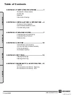
Страница 4: ...D VIEW 7 Composite Repair Parts Drawing Composite Repair Parts List Material Codes SECTION 4 AIR END 10 Air Distribution Valve Assembly Air Valve with Stroke Indicator Assembly Pilot Valve Assembly Intermediate Assembly SECTION 5 WET END 13 Diaphragm Drawings Diaphragm Servicing SECTION 7 WARRANTY CERTIFICATES 15 Warranty EC Declaration of Conformity Machinery EC Declaration of Conformity ATEX 4 M...

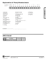
Страница 5: ...ERSAMATIC PRODUCT LINE B Anti clog Flap PUMP SIZE 20 2 CHECK VALVE TYPE F Flap Valve WET END MATERIALS A Aluminum NON WETTED MATERIAL A Aluminum DIAPHRAGM MATERIAL B Nitrile Buna N Neoprene R Santoprene BACKUP DIAPHRAGM 0 None CHECK VALVE MATERIAL S Stainless Steel SEAT MATERIAL S Stainless Steel AIR VALVE 0 Standard Match Ground AIR VALVE OPTION 0 None B Stainless Steel Sleeve Brass Spool EXHAUST...

Страница 6: ...oroplastic with excellent chemical resistance Excellent for UV applications High tensile strength and impact resistance 250 F 121 C 0 F 18 C Santoprene Injection molded thermoplastic elastomer with no fabric layer Long mechanical flex life Excellent abrasion resistance 275 F 135 C 40 F 40 C UHMW PE A thermoplastic that is highly resistant to a broad range of chemicals Exhibits outstanding abrasion...

Страница 7: ...2 61 66 2 61 66 OPTIONAL VERTICAL SUCTION PORT OPTIONAL VERTICAL DISCHARGE PORT 2 55 65 2 64 67 17 69 449 2 59 66 7 06 179 13 56 344 2 NPT 2 BSPT SUCTION PORT 2 NPT 2 BSPT DISCHARGE PORT 3 4 NPT AIR INLET 13 00 330 16 00 406 10 25 260 14 00 355 11 00 279 8 88 226 5 28 134 8X 50 13 THRU 1 NPT EXHAUST PORT Dimensional Drawings Model VMB20F 7 www versamatic com 1 PUMP SPECS ...

Страница 8: ... the check valves ball or flap orientation The pump primes as a result of the suction stroke The suction stroke lowers the chamber pressure P3 increasing the chamber volume This results in a pressure differential necessary for atmospheric pressure P4 to push the fluid through the suction piping and across the suction side check valve and into the outer fluid chamber Suction side stroking also init...

Страница 9: ...rication The air distribution system is designed to operate WITHOUT lubrication This is the standard mode of operation If lubrication is desired install an air line lubricator set to deliver one drop of SAE 10 non detergent oil for every 20 SCFM 9 4 liters sec of air the pump consumes Consult the Performance Curve to determine air consumption Air Line Moisture Water in the compressed air supply ma...

Страница 10: ...lds Clean manifolds to allow proper air flow Deadhead system pressure meets or exceeds air supply pressure Increase the inlet air pressure to the pump Pump is designed for 1 1 pressure ratio at zero flow Does not apply to high pressure 2 1 units Cavitation on suction side Check suction move pump closer to product Lack of air line size PSI CFM Check the air line size length compressor capacity Exce...

Страница 11: ...6 V314 000 Air End Refurbishment Kit Bumpers Bushings Gaskets O rings Seals Plungers and Retaining Rings 476 V397 360 Wet End Kit Nitrile Diaphragms Nitrile Hinge Pads Nitrile Wear Pads sealing washers 476 V397 363 Wet End Kit FKM Diaphragms FKM Hinge Pads FKM Wear Pads sealing washers 476 V397 364 Wet End Kit EPDM Diaphragms EPDM Hinge Pads EPDM Wear Pads sealing washers 476 V397 365 Wet End Kit ...

Страница 12: ...p 1 4 x 20 8 29 560 001 360 O ring 2 30 560 022 360 O ring 2 31 570 009 360 Pad Wear Buna 2 570 009 363 Pad Wear FKM 2 570 009 364 Pad Wear EPDM 2 also used w Santoprene 2 570 009 365 Pad Wear Neoprene also used with Hytrel Urethane 2 32 570 021 360 Pad Hinge Buna 4 570 021 363 Pad Hinge FKM 4 570 021 364 Pad Hinge EPDM also used w Santoprene 4 570 021 365 Pad Hinge Neoprene also used with Hytrel ...

Страница 13: ...essed Fibre 426 Blue Gard 440 Vegetable Fibre 500 Delrin 500 502 Conductive Acetal ESD 800 503 Conductive Acetal Glass Filled 506 Delrin 150 520 Injection Molded PVDF Natural color 540 Nylon 542 Nylon 544 Nylon Injection Molded 550 Polyethylene 551 Glass Filled Polypropylene 552 Unfilled Polypropylene 555 Polyvinyl Chloride 556 Black Vinyl 557 Conductive Polypropylene 558 Conductive HDPE 570 Rulon...

Страница 14: ...MPORTANT Read these instructions completely before installation and start up It is the responsibility of the purchaser to retain this manual for reference Failure to comply with the recommendations stated in this manual will damage the pump and void factory warranty 1 A 1 B 1 B 1 C 1 E 1 F 1 G 1 C 1 E 1 F 1 G 1 D Air Distribution Valve Servicing See repair parts drawing remove screws Step 1 Remove...

Страница 15: ...h O Rings 1 3 E 560 023 360 O Ring Spool 2 3 F 675 037 080 Retaining Ring 1 3 A 3 F 3 D 3 B 3 C 3 E Pilot Valve Servicing With Pilot Valve removed from pump Step 1 Remove snap ring 3 F Step 2 Remove sleeve 3 B inspect O Rings 3 C replace if required Step 3 Remove spool 3 D from sleeve 3 B inspect O Rings 3 E replace if required Step 4 Lightly lubricate O Rings 3 C and 3 E Reassemble in reverse ord...

Страница 16: ...out on the exploded view Repeat procedure for second side assembly Allow a minimum of 15 minutes to elapse after torquing then re torque the assembly to compensate for stress relaxation in the clamped assembly Step 6 Thread one assembly onto the diaphragm rod with sealing washer when used and bumper Step 7 Install diaphragm rod assembly into pump and secure by installing the outer chamber in place...

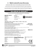
Страница 17: ...st fabriqué selon les normes harmonisées suivantes afin d en garantir la conformité Este producto cumple con las siquientes directrices de la comunidad europa Dieses produkt ist nach folgenden harmonisierten standards gefertigtworden die übereinstimmung wird bestätigt Questo prodotto ha utilizzato i seguenti standards per verificare la conformita De volgende geharmoniseerde normen werden gehanteer...

Страница 18: ... Applied II 2 G Ex h IIC T5 225 C T2 Gb II 2 D Ex h IIIC T100 C T200 C Db Metal pump models with external aluminum components E series Versa Surge surge suppressors VTA Series 2 AODD Pumps Technical File No 20310400 1410 MER On File With DEKRA Certification B V 0344 Hazardous Location Applied I M2 Ex h Mb II 2 G Ex h IIC T5 225 C T2 Gb II 2 D Ex h IIIC T100 C T200 C Db Metal pump models with no ex...

Отзывы: