


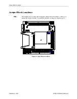


Jumper Block Locations
EPM-4 Reference Manual
Reference
–
23
J
UMPER
S
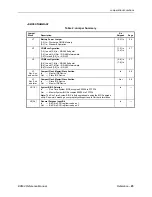
UMMARY
Table 2: Jumper Summary
Jumper
Block
Description
As
Shipped
Page
V1
Battery Power Jumper
[1-2] In – Discharge CMOS Memory
[2-3] In – Standard Operation
[2-3] In
26
V2
COM3 configuration
[1-2] In and [3-4] In – RS-485 Endpoint
[1-2] In and [3-4] Out – RS-485 Intermediate
[1-2] Out and [3-4] In – RS-422
[1-2] In
[3-4] In
27
V2
COM4 configuration
[5-6] In and [7-8] In – RS-485 Endpoint
[5-6] In and [7-8] Out – RS-485 Intermediate
[5-6] Out and [7-8] In – RS-422
[5-6] In
[7-8] In
27
V3
Rev. 4.xx
and earlier
CompactFlash Master/Slave Section
In
— Master IDE Device
Out — Slave IDE Device
In
28
V3
Rev. 5.xx
and later
CompactFlash Master/Slave Section
In
— Slave IDE Device
Out — Master IDE Device
Out
28
V4[1-2]
System BIOS Selector
In
— Run Time System BIOS occupies E0000h to FFFFFh
Out — Master System BIOS occupies E0000h to FFFFFh
Note:
The Run Time System BIOS is field upgradeable using the BIOS upgrade
utility. See www.VersaLogic.com/private/lynxsupport.asp for further information.
In —
V4[3-4]
General Purpose Input Bit
In
— Bit D0 in SCR register reads as 1
Out — Bit D0 in SCR register reads as 0
In —
Содержание EPM-4
Страница 2: ...EPM 4 AMD ÉlanSC520 processor module with 10 100 Ethernet and PC 104 Plus interface MEPM4 ...
Страница 5: ......
Страница 8: ...Table of Contents v Appendix B References 45 ...
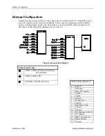
Страница 11: ...EPM 4 Block Diagram EPM 4 Reference Manual Introduction 3 EPM 4 Block Diagram ...
Страница 14: ......
Страница 24: ......
Страница 50: ......


