Interfaces and Connectors
EPM-32 Reference Manual
41
USB Interface
The USB interface on the EPM-32 is UHCI (Universal Host Controller Interface) and EHCI
(Enhance Host Controller Interface) compatible, which provides a common industry
software/hardware interface.
The USB controller can be enabled or disabled in CMOS Setup. The USB controller uses PCI
interrupt “INTA#” and “INTD#”. CMOS Setup is used to select the IRQ line routed to each PCI
interrupt line.
This connector uses IEC 61000-4-2-rated TVS components to help protect against ESD damage.
There are two USB ports accessible on JS5. See the
Connector Location Diagrams
on page 15
for connector and cable information, and the table on page 28 for JS5 pinout information.
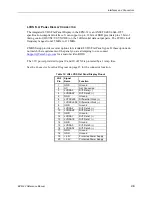
The pinout below applies to the USB connectors on the CBR-8001 breakout cable.
Table 15: JD USB 2.0 Interface Connector
JD Pin
Signal
Name
Function
1
USBP0PWR
+5V (Protected)
2
USBP0
–
Channel 0 Data
–
3
USBP0+
Channel 0 Data +
4
GND
Cable Shield
5
GND
Ground
6
GND
Ground
7
GND
Cable Shield
8
USBP1+
Channel 1 Data +
9
USBP1
–
Channel 1 Data
–
10
USBP1PWR
+5V (Protected)
Warning!
The 10-pin USB header on CBR-8001 is not numbered in the conventional manner
for dual-row headers. Care must be taken to attach the USB adapter cables, as
shown in Figure 14, to prevent voltage reversal.
Figure 14. USB Header Pin Orientation
1 6
5 10
USB
Connector A
USB
Connector B
Red Wire
Red Wire

