


Interfaces and Connectors
EPM-32 Reference Manual
33
CompactFlash
Connector JS6 provides a socket for a Type I or Type II CompactFlash (CF) module. This IDE
based interface operates on a separate channel than the IDE interface at connector JS4 (IDE 2 in
CMOS Setup). The CF interface supports operation in DMA mode.
The following CF modules have been tested and qualified as bootable devices by VersaLogic. As
an IDE device, there is no limitation to the capacity of CF module that can be used.
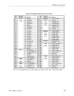
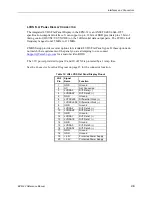
Table 10. Qualified Bootable CF Modules
Manufacturer
Density
Mfg Part Number
Hagiwara
1 GB
CF1-1GMDG(H00AA)
Hagiwara
512 MB
CF1-512MDG(H00AA)
Silicon Systems
256 MB
SSD-C25M-3012, -3500*
Silicon Systems
256 MB
SSD-C25MI-3012, -3500
Silicon Systems
1 GB
SSD-C01G-3012, -3500
Silicon Systems
2 GB
SSD-C02G-3012, -3500
Silicon Systems
2 GB
SSD-C02GI-3012, -3500
Silicon Systems
4 GB
SSD-C04GI-3012, -3500
Silicon Systems
512 MB
SSD-C51M-3012, -3500
Silicon Systems
512 MB
SSD-C51MI-3012, -3500
* Suffix of -3500 denotes RoHS-compliant module.
Programmable LED
Connector JS5 includes an output signal for a software controlled LED. Connect the cathode of
the LED to JS5 pin A28; connect the anode to +5V. An on-board resistor limits the current to 15
mA when the circuit is turned on. A programmable LED is provided on the CBR-8001 breakout
cable.
To turn the LED on and off, set or clear bit D7 in I/O port 1D0h (or 1E0h). When changing the
register, make sure not to alter the value of the other bits.
The following code examples show how to turn the LED on and off. Refer to page 47 for further
information.
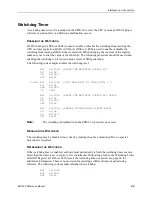
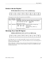
LED On
LED Off
MOV
DX,1D0H
MOV
DX,1D0H
IN
AL,DX
IN
AL,DX
OR
AL,80H
AND
AL,7FH
OUT
DX,AL
OUT
DX,AL
Note:
The LED is turned on by the BIOS during system startup. This causes the light to
function as a "power on" indicator if it is not otherwise controlled by user code.
The BIOS also flashes the LED in sync with “Beep Codes” when an error occurs.