


9
Defiant
®
1975CE Non-Catalytic / Catalytic Woodburning Stove
30005554
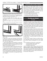
Floor protection for Fireplace installations
Do not assume that your fireplace hearth is completely
noncombustible.
Many fireplace hearths do not meet the “completely non-
combustible” requirement because the brick or concrete in
front of the fireplace opening is supported by heavy wood
framing. (Fig. 11) Because heat passes through brick or
concrete readily, it can easily pass through to the wood.
As a result, such fireplace hearths can be a fire hazard and
are considered a combustible floor.
Keep in mind, also, that many raised hearths will extend
less than the required clearance from the front of the heater
when it is installed. In such cases, sufficient floor protection
as described above must be added in front of the hearth to
satisfy the minimum floor protector requirement from the
front of the stove: 406 mm (16”) from the front.
ST247
Rear exit floor dgrm
12/14/99 djt
Wood framing requires protec-
tion from radiant heat
ST47e
Fig. 11
Combustible supporting timbers may lie beneath fire-
place hearths, requiring additional floor protection.
Hearth rugs do not satisfy the requirements for floor pro-
tection.
keep the Stove a Safe Distance
from Surrounding Materials
Both a stove and its chimney connector radiate heat in all
directions when operating, and dangerous overheating
of nearby combustible materials can occur if they are too
close to the heat. A safe installation requires that adequate
clearance be maintained between the hot stove and its
connector and nearby combustibles.
Clearance is the distance between either your stove (mea-
sured from the bottom edge of the stove’s top plate) or
chimney connector, and nearby walls, floors, the ceiling,
and any other fixed combustible surface. Your stove has
special clearance requirements that have been established
after careful research and testing to both US and European
standards. These clearance requirements must be strictly
observed.
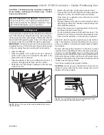
hearths
This appliance must be installed on to hearth that meets
the requirements of Part J of the Building Regulations 000
(Combustion Appliances and Fuel Storage Systems). This
can be achieved by ensuring that the hearth is constructed
and sized in accordance with the guidelines included in sec-
tion of approved document ‘J’. The size and clearances
of the hearth are as follows:
The constructed hearth should be constructed in ac-
cordance with the recommendations in document J, and
should be of minimum width 840 mm and minimum depth
840 mm (if a free standing hearth b) above) or a minimum
projection of 150 mm from the jamb (if a recessed hearth
a) above).
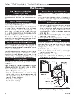
Unless the stove hearth is completely noncombustible,
the bottom heat shield
should be installed to
provide radiant protec-
tion for framing which
may be below the
hearth. (Fig. 11)
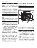
Costructional Hearth
Dimensions as below
At least
300 mm
At least 150 mm
or to a suitable
heat resistant wall
At least
150 mm
Hearth Surface
Free of Com-
bustible Material
Perimeter should be
clearly marked e.g.
edge of superimposed
hearth
Perimeter should be
clearly marked e.g.
edge of superimposed
hearth
Appliance
Doors
Appliance
Doors
ST91
Fig. 10
Noncombustible hearth surface dimensions.
a) Fireplace recess
b) Free standing


