VA-P_man_Rev06-2013_UK_(uk) | 18.06.2013
8
mounting
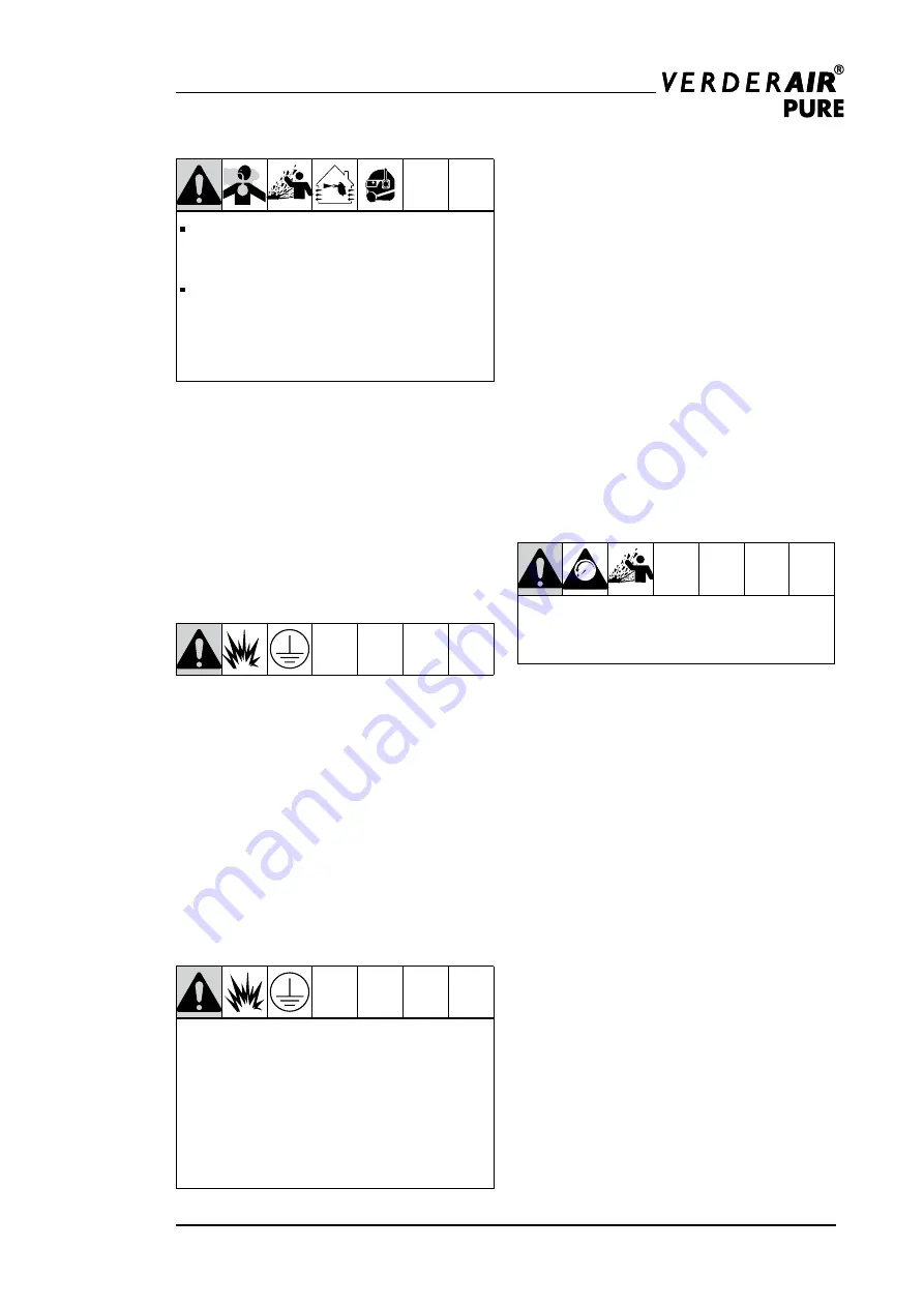
The pump exhaust air may contain
contaminants. Ventilate to a remote area.
See Air Exhaust Ventilation on page 9.
Never move or lift a pump under
pressure. If dropped, the fluid section may
rupture. Always follow the Pressure Relief
Procedure on page 10 before moving or
lifting the pump.
1. Be sure the mounting surface can support
the weight of the pump, hoses and
accessories, as well as the stress caused
during operation.
2. For ease of operation and service, mount
the pump so air inlet, fluid inlet and fluid
outlet ports are easy accessible.
3. All VA-P pumps are supplied with
adjustable feet.
grounding
The equipment must be grounded.
Grounding reduces the risk of static and
electric shock by providing an escape
wire for the electrical current due to static
build up or in event of a short circuit. In
the centre housing of electrical conductive
pumps (pump code VA-Pxx GG and VA-Pxx
UU) a grounding connection is included.
Check your system electrical continuity
after the initial installation. Set up a regular
schedule for checking continuity to be sure
proper grounding is maintained.
Only pumps made from conductive material
are having a grounding connection.
Standard PE and PTFE pumps are
not
conductive.
Never
use a non-conductive
pump with non-conductive flammable
fluids. Follow your local fire codes. When
pumping flammable fluids,
always
ground
the entire fluid system as described.
Air Line
See recommended installation drawing
on page 7.
1. Install an air regulator and gauge. Set
pressure of the driving air should be
limited to the pressure required to run
the pump on the desired working point.
Setting the pressure too high will cause
higher wear of the pump and will increase
the compressed air consumption. The
fluid stall pressure will be the same as the
setting of the air regulator.
2. If the air regulator do not have a bleed off
function to relieve trapped air, or the air
regulator is not placed close to the pump,
locate a bleed-type master air-valve close
to the pump. Be sure the valve is easily
accessible from the pump.
MPa/bar/PSI
Trapped air can cause the pump to cycle
unexpectedly, which could result in serious
injury from splashing.
3. The master air valve will be used to
regulate the flow rate of the air to the
pump. By using a needle valve, it is
possible to regulate the pump speed even
at the lower end of the curves.
4. Install a grounded, flexible air hose
between the accessories and the pump
air inlet. The inner diameter of the hose
have to be the same diameter of the air
connection of the pump or bigger.


