Insert the new element through the glands and refit the compression collars. Their
centres should be approximately 40 mm from the end of the element. Firmly tighten
the gland cap, ensuring the element lies centrally between the chamber liner and the
insulation.
Reconnect the electrical leads, refit the chamber liner and back panel.
Reconnect the furnace to supply.
Check that the furnace is controlling properly to rule out the possibility that the previous
element failed because of a fault elsewhere in the control circuit.
Note on 208 V elements: these elements are marked “240 V 2000 W”. These
elements correctly give 1500 W when used at 208 V.
7.7
Fuse Replacement
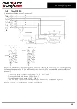
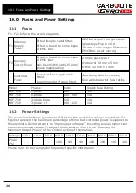
Fuses are marked on the wiring diagram with type codes, e.g. F1, F2. For more
information on fuses refer to section 10.0.
Depending on model and voltage, the different fuse types may or may not be fitted.
If any fuse has failed, it is advisable for an electrician to check the internal circuits.
Replace any failed fuses with the correct type. For safety reasons do not fit larger
capacity fuses without first consulting Carbolite Gero.
The fuses are located at the cable entry point. Remove the back panel or control box
back panel to gain access to the fuses.
21
7.0 Repairs and Replacements
Содержание CARBOLITE GERO HRF 7/45
Страница 28: ......
Страница 29: ...Notes Service Record Engineer Name Date Record of Work ...


