


Images
folder. This folder is created when a test is run and images are captured. This
folder contains all the captured test images in the format 'Date-Time-Temperature-
SequenceNumber.tif'.
4.7.4.11
File Formats
There are several files created when running the CAF software:
.tiff
Image Files. These files are stored in two different formats in the
'AutoAnalysisResults', 'AnalysisResults' and 'Images' folders.
'Date-Time-Temperature-SequenceNumber.tif'. These files are saved in the Images
folder and each file is approximately 1.8Mb.
'Test piece description plus the melt letters.tif'. These files are saved in the
'AutoAnalysisResults' and 'AnalysisResults' folder and each file is approximately 1.8Mb.
The '.tiff' image files can be imported into any Image editing program or Microsoft Word
or Excel for inclusion in test reports etc. The Results.csv and the Results.xml files
containing the temperature data can also be inserted into a Microsoft documents as a
table or opened as spread sheets.
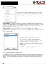
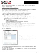
CaptureSettings.xml
. This file is created in the 'User Test Name' folder. It is a record
of the settings used when the test was first run. Time stamp will indicate when the test
was started.
AutoSettings.xml
. (Automatic Analysis) This file is created in the 'User Test Name'
folder. It is created every time the automatic analysis 'Start' button is selected. The data
contained within this file is for software functionality only and is not relevant to the user.
Settings.xml
. This file is created in the 'User Test Name' folder. It is written during the
analysis phase. When any settings are changed while in Analysis mode this file will be
updated. This could include changing test piece names, grid parameters, etc. time
stamp will indicate the last change.
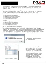
AutoResults.xml
. (Automatic Analysis) This file is created in the 'User Test Name'
folder when the automatic analysis is complete. This holds the data from the automatic
analysis results.
Note
: AutoResults.xml and Results.xml look very similar in their layout but they are not
interchangeable.
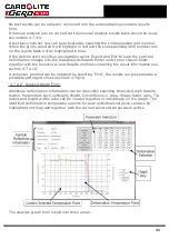
Results.xml
(Manual Analysis) This file is created in the 'User Test Name' folder when
test piece results are saved. This holds the data from the manual results form, i.e.
Temperature, filename for the original image at that temperature, modified filename
(test piece description plus the melt letters) for the image at that temperature, plus grid
position information. If you move the grid, for example for test piece one between
saving each temperature, this information will be saved here.
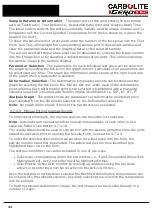
Results.xlsx
. This file is created in the 'AnalysisResults' or the 'AutoAnalysisResults'
folder when the results table is saved and is in the same format as the first page of the
analysis report printout.
Results.csv.
This file is also created in the 'AnalysisResults' or the 'AutoAnalysisResults'
folder and holds the same information as the Results.xlsx file but as comma separated
value format.
44
Содержание CARBOLITE GERO CAF G5
Страница 63: ...Fig 3 Front Tube Seal Assembly Fig 4 Door Arm Assembly 63 ...
Страница 64: ...Fig 5a Camera Mounting Bracket Fig 5b Lens and Camera Assembly 64 ...
Страница 65: ...Fig 5c Sliding the Camera Mounting Bracket Assembly onto the Door Arm 65 ...
Страница 66: ...Fig 5d Securing the Camera Mounting Bracket Assembly to the Door Arm 66 ...
Страница 67: ...Fig 5e Mounting the Lens and Camera Assembly 67 ...
Страница 68: ...Fig 5f Lens and Camera Assembly in Position 68 ...
Страница 69: ...Fig 6a Rear View of the Standard CAF G5 Furnace Showing Brick Box Assembly 69 ...
Страница 70: ...Fig 6b Rear View of the CAF G5 Biomass Furnace with Rear Illumination Showing Brick Box Assembly 70 ...
Страница 71: ...Fig 7 Front Tube Seal Position 71 ...
Страница 72: ...Fig 8 Tube End Seal Assembly Tightening Sequence Fig 9 Work Tube Front Support 72 ...
Страница 73: ...Fig 10 Fitting the Door Arm Assembly Fig 10a Adjusting the Door Arm Assembly 73 ...
Страница 74: ...Fig 11a Furnace Case and Controls 74 ...
Страница 75: ...Fig 11b Gas Inlet Pipe Fig 12 Positioning the Furnace 75 ...
Страница 76: ...Fig 13a Positioning Samples on the Sample Carrier Fig 13b Loading Samples into the Mouth of the Work Tube 76 ...
Страница 77: ...Fig 13c Loading Samples into the Work Tube 77 ...
Страница 78: ...Fig 16 File Folder 78 ...
Страница 79: ...Fig 17 Door Arm Assembly Exploded View 79 ...
Страница 82: ...SST DT HT FT Fig 18 Report Sheet Page 2 Side View Plan View Fig 19 Formed Wire Sample 82 ...
Страница 83: ...Fig 20 Sample Carrier Sample Tiles and Sample Positions 83 ...
Страница 84: ...Fig 21a Coal and Coke Test Piece Mould Fig 21b Biomass Test Piece Mould and Hand Press 84 ...
Страница 85: ...Fig 22 Sample Loading Tool Fig 23 Camera Ethernet Connection 85 ...
Страница 86: ...Fig 24 LED Driver Connection 86 ...
Страница 87: ...Notes Service Record Engineer Name Date Record of Work ...


