


to 1200 °C, the aperture can be set to a suitable position to maximise the exposure
range e.g. f8.
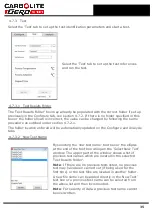
3.9.2
Adjusting the Lens.
To adjust the lens for the ideal image quality the furnace and computer must be
connected, see section 3.10 and the software must be running in configure mode see
section 4.7.2. The image displayed in the image window is a real time image, so the
camera focus can easily be adjusted. The camera must be mounted as described
above.
Prepare a number of test samples and load into the work tube as described in section
4.5. Close the door and ensure it is securely closed using the swing bolts.
For there to be sufficient light in the work tube to allow image capture the furnace must
be either at a standby temperature of 450 °C with rear light activated (if available) or at
a standby temperature of 815 °C.
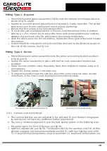
With the lens set at a suitable aperture, ideally f16 an image should now be displayed in
the software. Loosen the focus locking screw and with the focusing ring at the front of
the lens see fig 5b the image can be focused on the screen. It may be useful to take the
weight of the camera in one hand while focusing with the other. Once the image is
focused on the screen the focus locking screw can now be tightened (care must be taken
not to over-tighten these screws.)
Note
: As the furnace warms up the work tube will increase slightly in length causing the
camera focus to alter, it may be necessary to re-focus the camera during the initial Ash
Fusion test run. Once the camera is focused the focus ring can be locked in position
using the locking screw, unless the camera is disturbed it should not require re-focusing
during subsequent tests.
3.10
Computer Connections
Unpack the computer from its transit boxes and assemble in accordance with the
manufacturers instructions provided.
Connect the Ethernet cable from the Ethernet socket on the back of the furnace case to
the Ethernet socket on the back of the computer.
Connect the comms lead from the 'Comms Port' on the back of the furnace to the
comms port on the back of the computer.
Connect the Monitor DVI in lead to the socket on the rear of the computer via the DVI to
display port adaptor.
Connect the keyboard and mouse to a USB socket on the rear of the computer.
20
Содержание CARBOLITE GERO CAF G5
Страница 63: ...Fig 3 Front Tube Seal Assembly Fig 4 Door Arm Assembly 63 ...
Страница 64: ...Fig 5a Camera Mounting Bracket Fig 5b Lens and Camera Assembly 64 ...
Страница 65: ...Fig 5c Sliding the Camera Mounting Bracket Assembly onto the Door Arm 65 ...
Страница 66: ...Fig 5d Securing the Camera Mounting Bracket Assembly to the Door Arm 66 ...
Страница 67: ...Fig 5e Mounting the Lens and Camera Assembly 67 ...
Страница 68: ...Fig 5f Lens and Camera Assembly in Position 68 ...
Страница 69: ...Fig 6a Rear View of the Standard CAF G5 Furnace Showing Brick Box Assembly 69 ...
Страница 70: ...Fig 6b Rear View of the CAF G5 Biomass Furnace with Rear Illumination Showing Brick Box Assembly 70 ...
Страница 71: ...Fig 7 Front Tube Seal Position 71 ...
Страница 72: ...Fig 8 Tube End Seal Assembly Tightening Sequence Fig 9 Work Tube Front Support 72 ...
Страница 73: ...Fig 10 Fitting the Door Arm Assembly Fig 10a Adjusting the Door Arm Assembly 73 ...
Страница 74: ...Fig 11a Furnace Case and Controls 74 ...
Страница 75: ...Fig 11b Gas Inlet Pipe Fig 12 Positioning the Furnace 75 ...
Страница 76: ...Fig 13a Positioning Samples on the Sample Carrier Fig 13b Loading Samples into the Mouth of the Work Tube 76 ...
Страница 77: ...Fig 13c Loading Samples into the Work Tube 77 ...
Страница 78: ...Fig 16 File Folder 78 ...
Страница 79: ...Fig 17 Door Arm Assembly Exploded View 79 ...
Страница 82: ...SST DT HT FT Fig 18 Report Sheet Page 2 Side View Plan View Fig 19 Formed Wire Sample 82 ...
Страница 83: ...Fig 20 Sample Carrier Sample Tiles and Sample Positions 83 ...
Страница 84: ...Fig 21a Coal and Coke Test Piece Mould Fig 21b Biomass Test Piece Mould and Hand Press 84 ...
Страница 85: ...Fig 22 Sample Loading Tool Fig 23 Camera Ethernet Connection 85 ...
Страница 86: ...Fig 24 LED Driver Connection 86 ...
Страница 87: ...Notes Service Record Engineer Name Date Record of Work ...


