Operation - 15
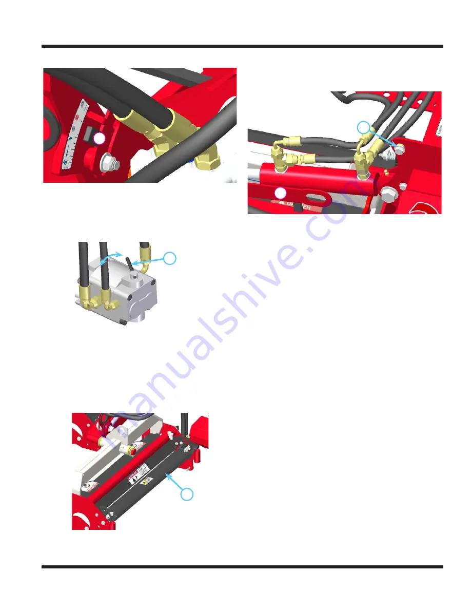
Reel Speed Control Lever
A
The position of the reel speed control lever (A)
determines the reel speed. To determine the correct
operating position, refer to the reel speed section of
Adjustments, or the back lapping section of Service.
Hydraulic Drive Motor Bypass Lever
A
Each hydraulic drive motor is equipped with a
bypass valve for disabling the motor during inspec-
tion or blade adjustment, or while back lapping the
other cutting units. To engage the motor, rotate the
bypass lever (A) towards the front to reach the run
position. To disengage the motor, rotate the bypass
lever towards the rear to reach the stop position.
Reel Discharge Deflector Shield
A
The reel discharge deflector shields (A) can be
adjusted for optimal clipping discharge. Rotate the
deflector shield downward to reduce or close the
discharge. Rotate the deflector shield upward to
increase or open the discharge.
Lift Arm Transport Lock
A
B
The lift arms for the left and right cutting units are
equipped with lift arm locking links (A) and locking
pins (B) for locking the lift arms in the raised posi-
tion. This is useful during transport and storage of
the reel mower. Refer to “transport of reel mower” in
the general machine operation section for instruc-
tions on the use of the lift arm locking links.
S.D.L.A. Controls
Primary S.D.L.A. Control Lever:
Pull the lever
to the left to raise the power unit front hitch and
reel mower. Push the lever to the right to lower the
power unit front hitch and reel mower. The control
lever must be in the ‘float’ (detent) position during
operation of the reel mower.
Secondary S.D.L.A. Control Lever:
Pull the lever
to the left to raise the left and right cutting unit lift
arms. Push the lever to the right to lower the cutting
unit lift arms. The control lever must be in the ‘float’
(detent) position during operation of the reel mower.
NOTE: Power units that are not equipped with an
auxiliary float, require the installation of float kit #
23.0111-7. Contact your authorized Ventrac dealer.
*
OPERATIONAL CONTROLS
* Refer to power unit operator’s manual for operation
of power unit controls.
Содержание MR740
Страница 28: ...PARTS Illustrated Parts 28 Use only original Ventrac replacement parts ILLUSTRATED DRAWING Hydraulic Drive ...
Страница 36: ...PARTS Illustrated Parts 36 Use only original Ventrac replacement parts ILLUSTRATED DRAWING Reel Head ...
Страница 38: ...PARTS Illustrated Parts 38 Use only original Ventrac replacement parts ILLUSTRATED DRAWING Front Rear Rollers ...


