SERVICE
Service - 20
Deck Belt Replacement
1. Detach the mower deck from the power unit.
2. Raise the mower deck shield.
3. Remove the old deck belt.
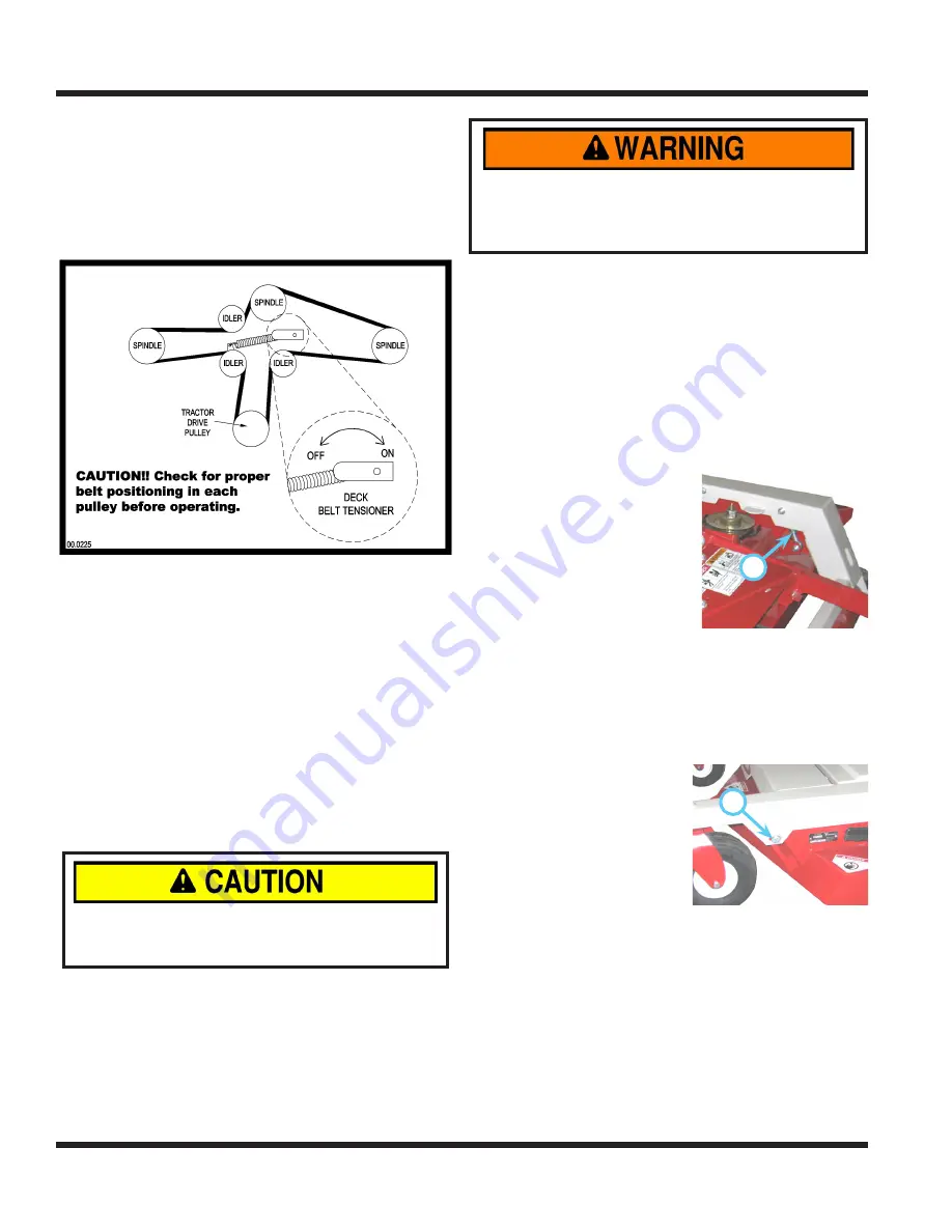
4. Install the new deck belt. Place belt into the pul-
ley system according to the belt diagram located
on the underside of the mower deck shield.
5. Ensure the belt is engaged in the groove of each
spindle pulley and around each of the flat idler
pulleys.
Tire Pressure
On mower decks equipped with pneumatic (inflatable)
tires, the tire pressure should be maintained at 6-8
psi. Pressure variance between left and right tires can
cause an uneven cut.
On mower decks with equipped with flat-free tires,
no tire pressure adjustments are required. The flat-
free cushioning tires provide a maintenance free,
consistent cutting height.
Deck Leveling Procedure
1.
Mower blades may be sharp. Always wear
safety glasses, leather gloves, and a long
sleeve shirt when working with mower blades.
Place the mower on a hard surface that is clean
and level. Detach the mower from the power unit.
2. Raise the mower deck to the highest cutting
height setting.
3. Block the tires and rear roller to prevent the
mower from rolling during leveling procedure.
4.
Ensure both front tires are inflated to the recom
-
mended tire pressure (See Tire Pressure section).
5.
Place blocks under 4) corners of the deck when
reaching under the mower deck to prevent the
deck from accidentally dropping and trapping or
crushing a bodily appendage.
Check the mower blades to ensure they are not
bent. To check for bent blades, move one blade
tip to the back of the deck and measure from the
floor to the blade. Rotate the other blade tip to
the back of the deck and measure again. If the
distance is different, the blade is bent and should
be replaced before continuing.
6. Go to one side of the deck. Turn the blade so
the tip is at the back of the deck. Measure the
distance from the floor to the blade.
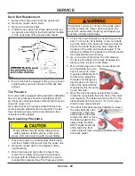
7.
A
Move to the other side of the mower deck and
turn that blade tip to the
back of the deck. If this
measures differently from
the first side, adjust the
threaded rod linkage (A)
directly above on the top
side of the deck until the
measurement is the same
as the first side.
8. Once the deck has been leveled side to side,
rotate the same blade tip to the front of the deck
and measure. The distance from the floor to the
blade should be the same to 1/8” (3 mm) lower
than the rear measurement.
9. If the front of the deck requires adjustment, loosen
B
the cross bolts (B) in the
carrier frame. Move the
bolts forward in the slots
to lower the deck or move
the bolts rearward in the
slots to raise the deck.
NOTE: slight movement
of the bolt in the front
carrier slots will make a significant difference in the
front deck height.
Содержание LM520
Страница 3: ...Blank Page ...
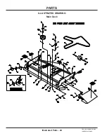
Страница 24: ...Illustrated Parts 24 Use only original Ventrac replacement parts ILLUSTRATED DRAWING Main Deck PARTS ...
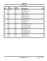
Страница 26: ...PARTS Illustrated Parts 26 Use only original Ventrac replacement parts ILLUSTRATED DRAWING Carrier Frame ...
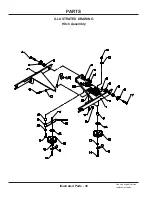
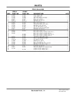
Страница 30: ...PARTS Illustrated Parts 30 Use only original Ventrac replacement parts ILLUSTRATED DRAWING Hitch Assembly ...
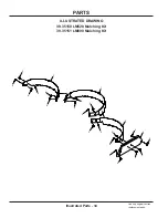
Страница 32: ...PARTS Illustrated Parts 32 Use only original Ventrac replacement parts ILLUSTRATED DRAWING Spindles Blades ...

