Ventrac KV552 Скачать руководство пользователя страница 18

Service - 18

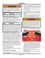
Cleaning and General Maintenance

For best results, and to maintain the finish of the 

KV552, clean or wash the V-blade to remove dirt, 

gravel, and salt deposits. Remove any ice or snow 

accumulations from the blade and frame. 

            Attention

To maintain the finish of the power unit and attach

-

ment, thoroughly wash the equipment after each 

use to remove any corrosive agents (e.g., salt). Fail-

ure to clean the equipment may result in corrosion 

of (including but not limited to) steel, aluminum, and 

electrical components. Equipment that will experi-

ence repeated exposure to corrosive agents should 

be pretreated with a corrosion preventative.

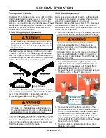
Cutting Edge Reversal/Replacement

If the cutting edges wear down near the blade frame 

structure, remove the cutting edges and flip over so 

the unworn top edge is now on the bottom. Reinstall 

the cutting edges onto the V-blade. When both sides 

of the cutting edges have been worn down, the cut-

ting edges will need to be replaced. Always reverse 

or replace both cutting edges at the same time.

NOTE: It is normal for the forward edge of the cut-

ting edges to wear faster than the rest of the cut-

ting edge, if the V-blade is used extensively in the 

swept forward position or in the left and right angled 

positions. To help minimize this effect, make sure 

the blade is level from side to side and that the skid 

shoes are adjusted properly.

Skid Shoe Replacement

Skid shoes should be replaced when wear surface is 

less then 1/8” thick.

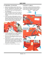
Leveling Blade - Side to Side

1. 

Make sure the power unit tires are inflated to the 

correct pressure.

2.  With the V-blade attached to the power unit and 

the power unit parked on a level surface, adjust 

both wings until they are straight out perpendicu-

lar to the power unit.

3.  Disengage the power unit’s weight transfer sys-

tem (if equipped).

4.  Lower the V-blade to the ground  and place the 

power unit’s primary S.D.L.A. lever in the float 

position by pushing it to the right until the detent 

engages.

5.  Check to see if the cutting edges are making even 

contact with the ground. If they are not making 

even contact, raise the blade all the way up and 

support securely with blocks or jack stands.

6. 


When making adjustments with the V-blade in the 

raised position, the V-blade hitch frame must be 

supported securely with blocks or jack stands.

Hydraulic drift or accidental release of hydraulic 

pressure could allow the V-blade to lower and 

trap a person or appendage, if the V-blade is not 

securely supported.

Loosen the 5) 1/2” bolts that fasten the center 

frame to the center hinge shaft and the center 

skid shoe.

7. 

1/2” Bolts

Sliding the center frame left or right in relationship 

to the center hinge shaft will raise or lower the 

outside corners of the blade wings. Moving the 

bottom to the right will raise the right side of the 

blade and lower the left side and moving it to the 

left will do the opposite. It may be helpful to use 

a jack or hoist  to lift the appropriate side of the 

blade and then tighten the 1/2” bolts.

8.  Repeat steps 4 and 5. If blade is still not level, 

repeat steps 6 and 7.

9.  When the blade is level, tighten the 1/2” bolts to 

80 ft-lbs (108 nm).

SERVICE

Always set the parking brake, shut off power 

unit engine, remove the ignition key, and ensure 

all moving parts have come to a complete stop 

before inspecting components or attempting any 

repair or adjustment.

            Attention

If any component requires replacement, use only 

original Ventrac replacement parts.

Содержание KV552

Страница 1: ...Operator s Manual Parts Drawings V Blade VENTRAC COM KV552 Revised 12 11 18 09 10060 Rev 05 Original Operator s Manual ...

Страница 2: ...___________________________________________________________________ _____________________________________________________________________ Dealer Phone Number _______________________________________________________________ Dealer Fax Number _________________________________________________________________ Model A ___________________________ Serial B ___________________________ Affix Part Serial Num...

Страница 3: ...afety 12 Hydraulic Safety 13 OPERATIONAL CONTROLS PAGE 15 Operational Control Locations 15 Blade Trip Control 15 Blade Wing Angle 15 Blade Wing Selection 15 GENERAL OPERATION PAGE 16 Daily Inspection 16 Attaching 16 Detaching 16 Operating Procedure 16 Transport of V blade 17 Blade Wing Angle Adjustment 17 Resetting the Blade Safety Trip 17 Skid Shoe Adjustment 17 SERVICE PAGE 18 Cleaning and Gener...

Страница 4: ...kid Shoes 22 Center Frame Hitch Frame 24 Safety Trip Pivot Springs 26 Hydraulic Cylinders Hoses Solenoid Valve 28 70 8044 Snow Containment Flap 30 70 8048 Polyurethane Cutting Edge 31 70 8045 6 Top Flare Extension 32 70 8047 6 Straight Edge Extension 33 70 8046 6 Extension with 6 Top Flare 34 WARRANTY PAGE 35 ...

Страница 5: ...uipment Keep this manual with the machine at all times The manual should remain with the machine even if it is sold If this manual becomes damaged or unreadable it should be replaced immediately Con tact your local Ventrac dealer for a replacement When using a Ventrac attachment be sure to read and follow the safety and operating instructions of both the power unit and the attachment being used to...

Страница 6: ...ughout this manual Right Hand and Left Hand is determined as if sitting on the power unit seat facing forward SIGNAL WORD DEFINITIONS Indicates a potentially hazardous situation which if not avoided could result in death or serious injury Indicates an imminently hazardous situation which if not avoided will result in death or serious injury This signal word is limited to the most extreme cases Ind...

Страница 7: ...y decals legible Remove all grease dirt and debris from safety decals and instructional labels If any decals are faded illegible or missing contact your dealer promptly for replacements When new components are installed be sure that current safety decals are affixed to the replacement components SAFETY A A B C D E ...

Страница 8: ...ription Part Number Quantity A Danger Pinching Hazard 00 0102 2 B Warning High Pressure Fluid Hazard 00 0103 1 C Warning Read Owner s Manual 00 0217 1 D Warning Pinch Point 00 0218 1 E Warning General Safety 00 0220 1 A B C D E ...

Страница 9: ...parts Be sure guards and shields are in proper working condition and are secured in place Make all necessary adjustments before operating machine Some pictures in this manual may show shields or covers opened or removed in order to clearly illustrate any instructions Under no circumstance should the machine be operated without these devices in place Alterations or modifications to this machine can...

Страница 10: ... in a building without adequate ventilation Do not touch the engine or the muffler while the engine is running or immediately after stopping the engine These areas may be hot enough to cause a burn Do not change the engine governor settings or over speed the engine Operating engine at excessive speed may increase the hazard of personal injury To reduce the hazard of fire keep the battery compartme...

Страница 11: ...und to improve stability While operating on slopes drive in an up and down direction when possible If turning is necessary while driving across slopes reduce speed and turn slowly in the downhill direction Assure a sufficient supply of fuel for continuous operation A minimum of one half tank of fuel is recommended Roadway Safety Operate with safety lights when operating on or near roadways Obey al...

Страница 12: ...nents while the engine is running or imme diately after stopping the engine These areas may be hot enough to cause a burn Allow the engine to cool before storing and do not store near an open flame Do not change the engine governor settings or over speed the engine Operating engine at excessive speed may increase the hazard of personal injury Springs may contain stored energy Use caution when dise...

Страница 13: ... tubes are in good condition Repair any leaks and replace any damaged or deteriorated hoses or tubes before starting the machine Hydraulic leaks can occur under high pressure Hydraulic leaks require special care and attention Use a piece of cardboard and a magnifying glass to locate sus pected hydraulic leaks Keep body and hands away from pinhole leaks or nozzles that eject high pressure hydraulic...

Страница 14: ...tial hazards Never travel at speeds that would cause injury to the operator or damage to the machine if the machine were to be stopped suddenly by an unseen immovable object Always operate the blade with the safety trip mechanism in the unlocked position unless digging in dirt at very low speeds Ensure that there are no objects between the back of the blade wings and the power unit When wings are ...

Страница 15: ...lade will not trip with the pin in the locked position Power units with 2 speed transaxles must be operated in low range The machine must be operated at very slow speed to prevent personal injury or damage to the machine if an immovable object is struck Blade Wing Angle Secondary S D L A Lever The secondary S D L A lever on the power unit controls the angle of the blade wings The blade wings can b...

Страница 16: ... the electric plug 6 Disengage the attachment hitch lock 7 Restart the power unit and back slowly away from the V blade Operating Procedure Before operation perform daily inspection and verify the skid shoes are set at the desired position If weight transfer is used set the weight transfer so the blade will lower to the ground in the float position If power unit is equipped with a 2 speed transaxl...

Страница 17: ...the operating position when it is moved away from the obstacle on which it is caught Skid Shoe Adjustment Skid shoes are provided to keep the cutting edge off the surface to be cleared especially when clearing snow from gravel driveways or roadways The skid shoe height is determined by the placement of spacer washers between the skid shoe and the skid shoe mount Extra spacer washers are stored on ...

Страница 18: ...d the power unit parked on a level surface adjust both wings until they are straight out perpendicu lar to the power unit 3 Disengage the power unit s weight transfer sys tem if equipped 4 Lower the V blade to the ground and place the power unit s primary S D L A lever in the float position by pushing it to the right until the detent engages 5 Check to see if the cutting edges are making even cont...

Страница 19: ... prior to leveling the blade 6 A B C Turn the adjusting bolt in to lower the outside corners of the blades and turn the adjusting bolt out to lower the front point of the blade 7 When the cutting edges are making even con tact with the ground tighten the jam nut to 100 ft lbs 136 nm 8 Loosen the 2 1 2 bolts C holding the lockout plate to the hitch frame and slide the plate in the mounting slots un...

Страница 20: ...nner Skid Shoe Fittings Hydraulic Hoses and Electric Cord Operation in severe conditions may require more frequent service intervals Grease until fresh grease is visible Spray Lubricant Maintenance Checklist KV522 V blade Maintenance Checklist o f L o c a t i o n s o f P u m p s A t 5 0 H o u r s A t 1 0 0 H o u r s A t 1 5 0 H o u r s A t 2 0 0 H o u r s A t 2 5 0 H o u r s A t 3 0 0 H o u r s A ...

Страница 21: ... unit 109 inches 276 9 cm with LE 3000 series power unit 99 5 inches 252 7 cm Weight 270 pounds 122 5 kg Blade Wing Angle Forward and Backward 30 degrees Features Independent right and left blade movement is controlled by separate cylinders Electric solenoid selects which blade will move Adjustable skid shoes Spring controlled blade safety trip mechanism Blade safety trip lockout for pushing dirt ...

Страница 22: ...Illustrated Parts 22 Use only original Ventrac replacement parts ILLUSTRATED DRAWING Blade Wings Cutting Edge Skid Shoes PARTS ...

Страница 23: ...5 29 GF0001 GREASE FTG 1 4 SAE ST 3 6 99 SF06 NUT SRF 3 8 16 USS 10 7 00 0103 DECAL HAZARD HIGH PRESS FLUID 1 8 79 0083 SHOE SKID ROUND ASM 2 9 90 0812 BOLT 1 2 13 USS X 1 1 2 4 10 95 08 WASHER FLAT 1 2 SAE 10 11 99 A08 LOCKNUT STOVER 1 2 13 USS 5 12 64 1492 BRACE CENTER SKID SHOE 1 14 64 1486 SHOE SKID CENTER RUNNER 1 15 90 0816 BOLT 1 2 13 USS X 2 1 16 00 0189 DECAL VENTRAC ORBITAL 1 17 00 0102 ...

Страница 24: ...PARTS Illustrated Parts 24 Use only original Ventrac replacement parts ILLUSTRATED DRAWING Center Frame Hitch Frame ...

Страница 25: ...ER SUBFRAME 1 4 99 A08 LOCKNUT STOVER 1 2 13 USS 4 5 95 08 WASHER FLAT 1 2 SAE 8 6 80 0351 SHAFT CENTER HINGE KV 1 7 90 0812 BOLT 1 2 13 USS X 1 1 2 2 8 02 HP0416 HAIRPIN 1 8 X 2 1 9 03 1020 CLEVIS PIN 5 8 X 2 1 2 1 10 90 0810 BOLT 1 2 13 USS X 1 1 4 2 11 64 1134 PLATE TRIP LOCK 1 12 62 1024 FRAME HITCH KV550 1 13 00 0217 DECAL WARNING READ OWNERS MAN 1 14 00 0220 DECAL GENERAL SAFETY 1 15 00 0100...

Страница 26: ...PARTS Illustrated Parts 26 Use only original Ventrac replacement parts ILLUSTRATED DRAWING Safety Trip Pivot Springs ...

Страница 27: ...EF PART NO DESCRIPTION QTY 1 99 SF0608 BOLT SRF 3 8 16 USS X 1 1 2 80 0352 SHAFT TRIP PIVOT 1 3 99 K0094 BOLT HANGER 3 8 16 X 4 4 4 41 0076 SPRING EXT 2 OD X 12 3 8 LG 4 5 90 1020 2 BOLT 5 8 11 USS X 2 1 2 TAP 1 6 99 E0076 NUT JAM 5 8 11 USS 1 7 99 SF06 NUT SRF 3 8 16 USS 1 8 92 06 NUT 3 8 16 USS 8 ...

Страница 28: ...PARTS Illustrated Parts 28 Use only original Ventrac replacement parts ILLUSTRATED DRAWING Hydraulic Cylinders Hoses Solenoid Valve ...

Страница 29: ... 100R17 AR 2 16 23 0136 1 VALVE DIRECTIONAL CONTROL 12V Serial 2001 3180 1 16 23 0164 VALVE DIRECTIONAL CONTROL 12V Serial 3181 1 17 25 6801 06 04 FITTING 90 ME 3 8 X 1 4 Serial 2001 3180 2 17 25 6801 06 06 FITTING 90 ME 3 8 X 3 8 Serial 3181 2 18 25 6400 06 04 FITTING M CONN 3 8 X 1 4 Serial 2001 3180 1 18 25 6400 06 06 FITTING M CONN 3 8 X 3 8 Serial 3181 1 19 99 SF04 NUT SRF 1 4 20 USS 2 20 56 ...

Страница 30: ...LUSTRATED DRAWING 70 8044 Snow Containment Flap REF PART NO DESCRIPTION QTY 1 90 0406 BOLT 1 4 20 USS X 3 4 10 2 95 04 WASHER FLAT 1 4 SAE 14 3 90 0408 BOLT 1 4 20 USS X 1 4 4 64 1143 CLAMP BELTING 34 X 1 2 5 44 0216 BELTING SNOW DEFLECTION 2 6 99 SF06 NUT SRF 3 8 16 USS 14 ...

Страница 31: ...ntrac replacement parts REF PART NO DESCRIPTION QTY 1 97 0616 BOLT CARRIAGE 3 8 X 2 10 2 64 1144 CLAMP POLY BACKER 26L 2 3 44 0217 CUTTING EDGE POLY 1 X 6 X 26L 2 4 99 SF06 NUT SRF 3 8 16 USS 10 ILLUSTRATED DRAWING 70 8048 Polyurethane Cutting Edge ...

Страница 32: ... ILLUSTRATED DRAWING 70 8045 6 Top Flare Extension REF PART NO DESCRIPTION QTY 1 99 SF0406 BOLT SRF 1 4 20 X 3 4 4 2 97 0608 BOLT CARRIAGE 3 8 X 1 6 3 60 0889 EXTENSION FLARE RH 1 4 99 SF06 NUT SRF 3 8 16 USS 6 5 60 0890 EXTENSION FLARE LH 1 6 99 SF04 NUT SRF 1 4 20 USS 4 ...

Страница 33: ... 3 8 X 1 6 3 78 0056 CUTTING EDGE 32 THRU HARD 2 4 99 SF0406 BOLT SRF 1 4 20 X 3 4 4 5 62 1028 FRAME 6 STRAIGHT WING EXT RH 1 6 62 1029 FRAME 6 STRAIGHT WING EXT LH 1 7 99 SF06 NUT SRF 3 8 16 USS 24 8 99 SF04 NUT SRF 1 4 20 USS 4 9 99 SF0606 BOLT SRF 3 8 16 USS X 3 4 4 10 97 0612 BOLT CARRIAGE 3 8 X 1 1 2 4 ILLUSTRATED DRAWING 70 8047 6 Straight Edge Extension ...

Страница 34: ...7 0610 BOLT CARRIAGE 3 8 X 1 1 4 10 2 97 0608 BOLT CARRIAGE 3 8 X 1 6 3 78 0056 CUTTING EDGE 32 THRU HARD 2 4 99 SF0406 BOLT SRF 1 4 20 X 3 4 4 5 62 1030 FRAME 6 FLARE WING EXT RH 1 6 62 1031 FRAME 6 FLARE WING EXT LH 1 7 99 SF06 NUT SRF 3 8 16 USS 24 8 99 SF04 NUT SRF 1 4 20 USS 4 9 99 SF0606 BOLT SRF 3 8 16 USS X 3 4 4 10 97 0612 BOLT CARRIAGE 3 8 X 1 1 2 4 ...

Страница 35: ...claim of breach of warranty shall be cause for cancellation or rescission of the contract of sale of any Ventrac equipment Proof of purchase may be required by the dealer to substantiate any warranty claim Only warranty work performed and submitted by an Authorized Ventrac Dealer may be eligible for warranty credit This warranty extends only to Ventrac commercial equipment operated under normal co...

Страница 36: ...set forth herein V P I shall not be liable for cost of removal or installation nor shall V P I be responsible for any direct indirect special or consequential damages of any nature In no event shall V P I be liable for any sum in excess of the price received for the goods for which liability is claimed There are no representations or warranties which have been authorized to the buyer of the Ventra...

Отзывы: