background image

PARTS

Illustrated Parts - 23

Use only original Ventrac 

replacement parts.

REF. 

PART NO. 

DESCRIPTION 

QTY.

1   . . . . . . . . . 44.0195  . . . . . . . . . . . . . . . . . . . .SHIELD, RUBBER   . . . . . . . . . . . . . . . . . . . . . . . . . . . . . . . . . . . . . . . . . . . . . . . . . . . . . . . . 3 

2   . . . . . . . . . 64.0958  . . . . . . . . . . . . . . . . . . . .BAR, RUBBER CLAMP   . . . . . . . . . . . . . . . . . . . . . . . . . . . . . . . . . . . . . . . . . . . . . . . . . . . . 2 

3   . . . . . . . . . 62.0911  . . . . . . . . . . . . . . . . . . . .FRAME, MAIN & HITCH . . . . . . . . . . . . . . . . . . . . . . . . . . . . . . . . . . . . . . . . . . . . . . . . . . . . 1 

4   . . . . . . . . . 60.0818  . . . . . . . . . . . . . . . . . . . .SHIELD, DRIVE BELT GEARBOX   . . . . . . . . . . . . . . . . . . . . . . . . . . . . . . . . . . . . . . . . . . . 1 

5   . . . . . . . . . 64.0957  . . . . . . . . . . . . . . . . . . . .STAND, SUPPORT . . . . . . . . . . . . . . . . . . . . . . . . . . . . . . . . . . . . . . . . . . . . . . . . . . . . . . . . 1 

6   . . . . . . . . . 03.0009  . . . . . . . . . . . . . . . . . . . .PIN, SAFETY SNAP 1/4 X 1-3/8 . . . . . . . . . . . . . . . . . . . . . . . . . . . . . . . . . . . . . . . . . . . . . . 1
7   . . . . . . . . . 99.SF0405-1  . . . . . . . . . . . . . . . .BOLT, SMF 1/4-20 X 5/8  . . . . . . . . . . . . . . . . . . . . . . . . . . . . . . . . . . . . . . . . . . . . . . . . . . . . 9 

8   . . . . . . . . . 99.A04 . . . . . . . . . . . . . . . . . . . . .LOCKNUT, STOVER 1/4-20 USS   . . . . . . . . . . . . . . . . . . . . . . . . . . . . . . . . . . . . . . . . . . . . 9 

9   . . . . . . . . . 99.SF0404   . . . . . . . . . . . . . . . . .BOLT, SRF 1/4-20 X 1/2   . . . . . . . . . . . . . . . . . . . . . . . . . . . . . . . . . . . . . . . . . . . . . . . . . . . . 2 

10   . . . . . . . . 99.SF04   . . . . . . . . . . . . . . . . . . .NUT, SRF 1/4-20 USS . . . . . . . . . . . . . . . . . . . . . . . . . . . . . . . . . . . . . . . . . . . . . . . . . . . . . . 8 

11 . . . . . . . . . 99.SF05   . . . . . . . . . . . . . . . . . . .NUT, SRF 5/16-18 USS . . . . . . . . . . . . . . . . . . . . . . . . . . . . . . . . . . . . . . . . . . . . . . . . . . . . . 2 

12   . . . . . . . . 60.0816  . . . . . . . . . . . . . . . . . . . .SHIELD, MAIN DRIVE COVER  . . . . . . . . . . . . . . . . . . . . . . . . . . . . . . . . . . . . . . . . . . . . . . 1
13   . . . . . . . . 60.0817  . . . . . . . . . . . . . . . . . . . .SHIELD, BOTTOM FINAL BELTS  . . . . . . . . . . . . . . . . . . . . . . . . . . . . . . . . . . . . . . . . . . . . 1 

14   . . . . . . . . 64.0956  . . . . . . . . . . . . . . . . . . . .COVER, ROTOR OPENING   . . . . . . . . . . . . . . . . . . . . . . . . . . . . . . . . . . . . . . . . . . . . . . . . 1 

15   . . . . . . . . 00.0192  . . . . . . . . . . . . . . . . . . . .DECAL, V-DECAL DIE CUT BLUE   . . . . . . . . . . . . . . . . . . . . . . . . . . . . . . . . . . . . . . . . . . . 1 

16   . . . . . . . . 00.0101  . . . . . . . . . . . . . . . . . . . .DECAL, HAZARD-MOVING PART   . . . . . . . . . . . . . . . . . . . . . . . . . . . . . . . . . . . . . . . . . . . 1 

17   . . . . . . . . 00.0123  . . . . . . . . . . . . . . . . . . . .DECAL, KEEP HANDS & FEET CLEAR  . . . . . . . . . . . . . . . . . . . . . . . . . . . . . . . . . . . . . . . 1 

18   . . . . . . . . 00.0102  . . . . . . . . . . . . . . . . . . . .DECAL, DANGER-PINCHING HAZARD   . . . . . . . . . . . . . . . . . . . . . . . . . . . . . . . . . . . . . . 1
19   . . . . . . . . 00.0189  . . . . . . . . . . . . . . . . . . . .DECAL, VENTRAC ORBITAL  . . . . . . . . . . . . . . . . . . . . . . . . . . . . . . . . . . . . . . . . . . . . . . . 1 

20   . . . . . . . . 90.0412  . . . . . . . . . . . . . . . . . . . .BOLT, 1/4-20 USS X 1 1/2 . . . . . . . . . . . . . . . . . . . . . . . . . . . . . . . . . . . . . . . . . . . . . . . . . . . 1 

21   . . . . . . . . 99.SF0404-1  . . . . . . . . . . . . . . . .BOLT, SMF 1/4-20 X 1/2  . . . . . . . . . . . . . . . . . . . . . . . . . . . . . . . . . . . . . . . . . . . . . . . . . . . . 2 

22   . . . . . . . . 00.0100  . . . . . . . . . . . . . . . . . . . .DECAL, MADE IN USA . . . . . . . . . . . . . . . . . . . . . . . . . . . . . . . . . . . . . . . . . . . . . . . . . . . . . 1 

23   . . . . . . . . 00.0217  . . . . . . . . . . . . . . . . . . . .DECAL, WARNING READ OWNERS MAN   . . . . . . . . . . . . . . . . . . . . . . . . . . . . . . . . . . . . 1 


Main Frame & Shields

Содержание KC180

Страница 1: ...Operator s Manual Parts Drawings Stump Grinder VENTRAC COM KC180 Revised 12 14 18 09 10017 Rev 06 Original Operator s Manual ...

Страница 2: ..._________________________________________________________________ _____________________________________________________________________ Dealer Phone Number _______________________________________________________________ Dealer Fax Number _________________________________________________________________ Model A ____________________________ Serial B _____________________________ Affix Part Serial Nu...

Страница 3: ...Trailer Transport 10 Maintenance 11 Fuel Safety 11 Hydraulic Safety 12 KC180 Safety Procedures 13 SETUP PAGE 14 Mirror Installation 14 GENERAL OPERATION PAGE 15 Daily Inspection 15 Attaching 15 Detaching 15 Operating Procedure 16 SERVICE PAGE 17 Cleaning and General Maintenance 17 Belt Inspection 17 Belt Tension Adjustment 17 Belt Replacement 18 Cutter Teeth Rotation Sharpening 18 Lubrication Loca...

Страница 4: ...TABLE OF CONTENTS 4 PARTS PAGE 22 Main Frame Shields 22 Drive Pulleys 24 Mirror Bracket 26 WARRANTY PAGE 28 ...

Страница 5: ...d ing the operator s manual will help you become familiar with each specific piece of equipment Under standing the operator s manual will help you as well as others avoid personal injury and or damage to the equipment Keep this manual with the machine at all times The manual should remain with the machine even if it is sold If this manual becomes damaged or unreadable it should be replaced immedia...

Страница 6: ...ughout this manual Right Hand and Left Hand is determined as if sitting on the power unit seat facing forward SIGNAL WORD DEFINITIONS Indicates a potentially hazardous situation which if not avoided could result in death or serious injury Indicates an imminently hazardous situation which if not avoided will result in death or serious injury This signal word is limited to the most extreme cases Ind...

Страница 7: ...ls If any decals are faded illegible or missing contact your dealer promptly for replacements When new components are installed be sure that current safety decals are affixed to the replacement components Decal Description Part Number Quantity A Warning Moving Part Hazard 00 0101 1 B Danger Pinching Hazard 00 0102 1 C Danger Keep Hands Feet Clear 00 0123 1 D Warning Read Owner s Manual 00 0217 1 A...

Страница 8: ...parts Be sure guards and shields are in proper working condition and are secured in place Make all necessary adjustments before operating machine Some pictures in this manual may show shields or covers opened or removed in order to clearly illustrate any instructions Under no circumstance should the machine be operated without these devices in place Alterations or modifications to this machine can...

Страница 9: ...in a building without adequate ventilation Do not touch the engine or the muffler while the engine is running or immediately after stopping the engine These areas may be hot enough to cause a burn Do not change the engine governor settings or over speed the engine Operating engine at excessive speed may increase the hazard of personal injury To reduce the hazard of fire keep the battery compartmen...

Страница 10: ...und to improve stability While operating on slopes drive in an up and down direction when possible If turning is necessary while driving across slopes reduce speed and turn slowly in the downhill direction Assure a sufficient supply of fuel for continuous operation A minimum of one half tank of fuel is recommended Roadway Safety Operate with safety lights when operating on or near roadways Obey al...

Страница 11: ...nents while the engine is running or imme diately after stopping the engine These areas may be hot enough to cause a burn Allow the engine to cool before storing and do not store near an open flame Do not change the engine governor settings or over speed the engine Operating engine at excessive speed may increase the hazard of personal injury Springs may contain stored energy Use caution when dise...

Страница 12: ... tubes are in good condition Repair any leaks and replace any damaged or deteriorated hoses or tubes before starting the machine Hydraulic leaks can occur under high pressure Hydraulic leaks require special care and attention Use a piece of cardboard and a magnifying glass to locate sus pected hydraulic leaks Keep body and hands away from pinhole leaks or nozzles that eject high pressure hydraulic...

Страница 13: ...ngs vehicles or other objects of value Block access to the area prior to grind ing stumps Use plywood or equivalent shielding to protect nearby building or objects If access to the area cannot be prevented use plywood or equivalent shielding to protect pedestrian areas Stop grinding immediately if the cutter head strikes a rock or other solid object Damage to the cutting teeth or the cutter head m...

Страница 14: ...tance into the mirror attachment brackets and secure them with the tightener handles 4 Mount the mirror frame to the outer ends of the mirror arms For a trial setting select a hole near the center of the adjustment options Use the iden tical hole on the opposite side Fasten to the mirror arms with 2 1 4 x 1 1 2 bolts 4 1 4 flat wash ers and 2 1 4 lock nuts 5 Fasten the pivot holes in the ends of t...

Страница 15: ...tely engaged close the front hitch locking lever 3 Engage the parking brake and shut off the engine 4 Place the attachment belt onto the PTO drive pulley on the power unit Ensure the belt is prop erly seated in each pulley 5 Engage the PTO belt tension spring 6 Raise the stand to give maximum ground clear ance 7 Slide the mirror arms into the mirror attachment brackets mounted on the front frame o...

Страница 16: ...throttle to the desired engine RPM Slowly lower the stump grinder until it begins to cut Turn the power unit s steering wheel left and right to sweep the cutter head across the stump After each pass lower the grinder a little more and repeat the process If the grinder is lowered to much at one time it will not allow the power unit to be steered Lift the grinder slightly to continue side to side gr...

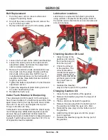
Страница 17: ...age the parking brake 2 Shut off the power unit engine and remove the key from the key switch 3 Loosen the four nuts A on the bearings on either side of the cutter head 4 A A B D Loosen the locking nut C on the back of the right adjustment plate Loosen the locking nut D on the front of the left adjustment plate 5 Tighten the belts by tightening the nut B on the front of the right adjustment plate ...

Страница 18: ...s 34 Nm Cutter teeth can be sharpened with the proper equip ment Sharpening carbide teeth requires a special process See your authorized Ventrac dealer for replacement parts or instructions for sharpening exist ing teeth Teeth that have lost more than 1 8 3 mm of original bite must be replaced Lubrication Locations Lubrication is required at the following locations using a lithium complex NLGI 2 g...

Страница 19: ...illegible or missing 4 Inspect belts for signs of damage or wear and replace as required 5 Inspect cutting teeth for wear and rotate sharpen or replace the teeth as necessary 6 Service all lubrication points and inspect gearbox oil level Wipe off excess grease or oil Removing the Stump Grinder from Storage 1 Clean the stump grinder to remove any accumu lated dust or debris 2 Inspect the stump grin...

Страница 20: ...spect for Loose Missing or Worn Components Grease Lubrication See Lubrication Section Check Gearbox Oil Level Maintenance Checklist Maintenance Checklist o f L o c a t i o n s o f P u m p s D a i l y A t 5 0 H o u r s A t 1 0 0 H o u r s A t 1 5 0 H o u r s A t 2 0 0 H o u r s A t 2 5 0 H o u r s A t 3 0 0 H o u r s A t 3 5 0 H o u r s A t 4 0 0 H o u r s A t 4 5 0 H o u r s A t 5 0 0 H o u r s A ...

Страница 21: ...all Width 27 inches 68 6 cm Overall Head Width 3 5 inches 8 9 cm Overall Cutter Head Diameter 18 inches 45 7 cm Cutter Head Speed 900 RPM Cutting Depth Below Ground Level 6 inches 15 2 cm Weight 170 pounds 77 1 kg Features 16 carbide teeth 3 sided and replaceable Convex mirror for safely viewing the operation from the power unit ...

Страница 22: ...Illustrated Parts 22 Use only original Ventrac replacement parts PARTS ILLUSTRATED DRAWING Main Frame Shields ...

Страница 23: ...SF0404 BOLT SRF 1 4 20 X 1 2 2 10 99 SF04 NUT SRF 1 4 20 USS 8 11 99 SF05 NUT SRF 5 16 18 USS 2 12 60 0816 SHIELD MAIN DRIVE COVER 1 13 60 0817 SHIELD BOTTOM FINAL BELTS 1 14 64 0956 COVER ROTOR OPENING 1 15 00 0192 DECAL V DECAL DIE CUT BLUE 1 16 00 0101 DECAL HAZARD MOVING PART 1 17 00 0123 DECAL KEEP HANDS FEET CLEAR 1 18 00 0102 DECAL DANGER PINCHING HAZARD 1 19 00 0189 DECAL VENTRAC ORBITAL 1...

Страница 24: ...PARTS Illustrated Parts 24 Use only original Ventrac replacement parts ILLUSTRATED DRAWING Drive Pulleys ...

Страница 25: ...R ROTOR Serial 1001 1230 1 20 79 0056 TOOTH STRAIGHT C BORED KC180 Serial 1001 1230 3 21 79 0055 TOOTH STRAIGHT TAPPED KC180 Serial 1001 1230 3 22 79 0054 TOOTH LEFT C BORED KC180 Serial 1001 1230 6 23 79 0053 TOOTH RIGHT TAPPED KC180 Serial 1001 1230 6 24 85 K030410 KEY 3 16 X 1 4 X 1 1 4 1 25 80 0376 ROTOR STUMPGRINDER KC180 Serial 1231 1 26 79 0085 TOOTH DEEP DISH W NUT Serial 1231 16 26 79 008...

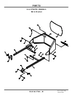
Страница 26: ...PARTS Illustrated Parts 26 Use only original Ventrac replacement parts ILLUSTRATED DRAWING Mirror Bracket ...

Страница 27: ...USS X 1 1 4 2 10 99 A04 LOCKNUT STOVER 1 4 20 USS 4 11 95 04 WASHER FLAT 1 4 SAE 8 12 90 0412 BOLT 1 4 20 USS X 1 1 2 4 13 99 K0062 MACHINE SCREW 10 32 X 1 2 4 14 05 0084 BUMPER CYLINDRICAL RUBBER 4 15 99 A1032N LOCKNUT NYLON 10 32 STAINLESS 4 16 60 0821 FRAME MIRROR MOUNT 1 17 47 0199 MIRROR ACRYLIC LENS 18 X 12 1 18 90 0508 BOLT 5 16 18 USS X 1 6 19 95 05 WASHER FLAT 5 16 SAE 6 20 99 SF05 NUT SR...

Страница 28: ...d no claim of breach of warranty shall be cause for cancellation or rescission of the contract of sale of any Ventrac equipment Proof of purchase may be required by the dealer to substantiate any warranty claim Only warranty work performed and submitted by an Authorized Ventrac Dealer may be eligible for warranty credit This warranty extends only to Ventrac commercial equipment operated under norm...

Страница 29: ...set forth herein V P I shall not be liable for cost of removal or installation nor shall V P I be responsible for any direct indirect special or consequential damages of any nature In no event shall V P I be liable for any sum in excess of the price received for the goods for which liability is claimed There are no representations or warranties which have been authorized to the buyer of the Ventra...

Отзывы: