


Page 13
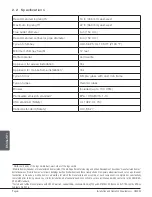
Installation and Operation Requirements - HES350
ENGLISH
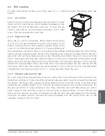
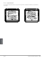
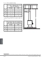
3.1.1 With Heat Shield AC02762
1
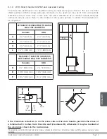
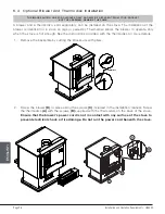
To reduce the clearances of an appliance using a single wall pipe connector, the use of a heat
shield certified with the single wall pipe connector to be used as close as 6" from combustible
materials must be used. Only in this case, the same clearances as a certified double wall pipe
connector can be used. Refer to the booklet in the screen options to obtain the dimensions to
be respected.
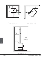
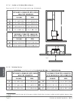
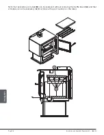
APPLIANCE CLEARANCES WITH DOUBLE
WALL PIPE CONNECTOR
DISTANCES
2
FROM DOUBLE WALL
PIPE CONNECTOR
Canada
USA
Canada
USA
A
2 ½" (64 mm)
2 ½" (64 mm)
D
7 ¼" (184 mm)
7 ¼" (184 mm)
B
2 ½" (64 mm)
2 ½" (64 mm)
E
13
⅜
" (340 mm)
13
⅜
" (340 mm)
C
2 ½" (64 mm)
2 ½" (64 mm)
F
13 ¼" (337 mm)
13 ¼" (337 mm)
A
B
E
D
CAN
48"
122 cm
US
36"
92 cm
48"
Flush
F
F
C
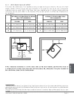
If the clearance reduction is on the same side as the door handle, position the stove at
a minimum of 6 inches from the side wall (clearance B), otherwise it may be located at
the clearance shown in the table above.
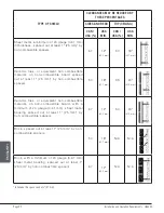
1
Note that to reduce the clearances of an appliance using a single wall pipe connector, the use of a heat shield certified with the single wall pipe
connector to be used as close as 6" from combustible materials must be used. Only in this case, the same clearances as a certified double wall
pipe connector can be used.
2
The pipe distances listed in this table refer to the distances obtained when the stove is installed in accordance with the appliance clearances above
mentioned.


