


4
9
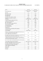
10 – LuminAir Turbo SKL 453419C
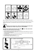
Make the appropriate electrical connections to the Turbo fan as shown in Figs 10 or 11 (See section B Wiring)
From the outside cut a 110mm hole in the soffit and secure the soffit grille using the screws provided. Extend the
ductwork provided between the soffit grille and the outlet of the turbo fan again securing with the duct ties
provided.
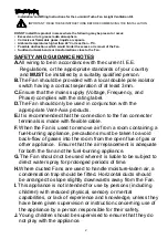
B. WIRING.
WARNING: THE FAN AND ANCILLARY CONTROL EQUIPMENT MUST BE ISOLATED FROM
THE POWER SUPPLY DURING THE INSTALLATION / OR MAINTENANCE.
N.B. THE TURBO FANS ARE DOUBLE INSULATED AND CARRY A MARK. THERE ARE NO EARTH
TERMINALS AND THESE FANS MUST NOT BE EARTHED.
1. Remove terminal box cover & screws and put to one side Fig. 9
2. Select and follow the appropriate wiring diagram (Fig. 10-11) & adjust the speed setting (Fig.14) if required.
The fan is factory set at high speed.
3. Check all connections have been made correctly and ensure all terminal connections and cable clamps are
securely fastened.
4. The cable entry must be made using the cable grommet provided
5. Replace terminal box cover & screws Fig.12
6. Ensure the impeller rotates and is free from obstructions.
1
2
3
4
5
6
7
8