5
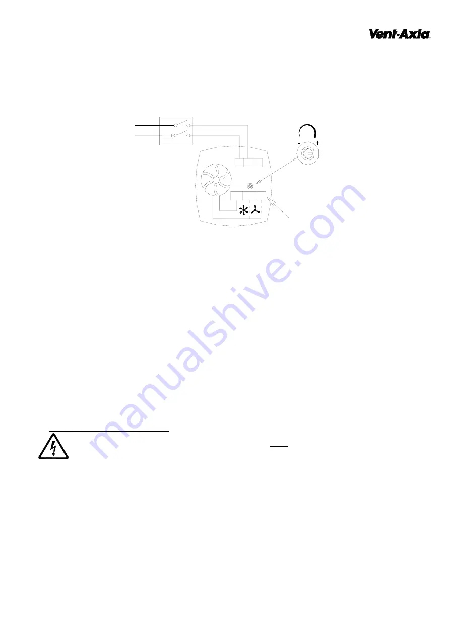
Fig. 4.
LoWatt U/KH
(45 91 25) Humidity Controlled Model.
Select the wiring configuration required for the Utility or Kitchen.
Humidity Set-Point Adjustment.
The Fan’s Humidity Set-Point is factory set to switch the fan on at 72%RH.
Before adjusting the Set-Point, switch off the Mains Supply.
1. Remove the Indoor Grille [A]. Loosen the screw (top middle) of the Grille, to release front grille gently lever the
Grille downwards away from the Inner Cover [B].
2. Remove Inner Cover [B]. Insert a small bladed screwdriver into the slot on the sides of the Cover, push the
release catch in and gently lever the cover away from the Base Housing [D].
3. To LOWER the Set-Point, turn the adjuster CLOCKWISE. This makes the fan more sensitive to RH%, i.e. the
fan will come on at a lower RH%.
4. To RAISE the Set-Point, turn the adjuster ANTI-CLOCKWISE. This makes the fan less sensitive to RH%,
i.e. the fan will come on at a higher RH%.
5. Replace the Inner Cover and Indoor Grille.
6. Reconnect the mains supply.
C.
SERVICING AND MAINTENANCE.
WARNING:
THE FAN AND ANCILLARY CONTROL EQUIPMENT MUST BE ISOLATED
FROM THE POWER SUPPLY DURING MAINTENANCE.
1. At intervals appropriate to the installation, the fan should be inspected and cleaned to ensure there is no build
up of dirt or other deposits.
2. Remove the Indoor Grille (See Section A : 2 for instructions) and wash in warm soapy water.
3. Wipe the shutter blades with a damp cloth until clean.
4. Replace the Grille.
The LoWatt fan has sealed for life bearings, which do not require lubrication.
1 Phase Supply
(220-240V 50Hz).
FUSE
Switched
Fused Spur
~
L
N
Humidity
Adjuster.
8V = Low Speed for
a Utility Room
12V = High Speed for
a Kitchen
12V
0V
8V
Fan
L N


