


B. WIRING.
WARNING: THE FAN AND ANCILLARY CONTROL EQUIPMENT MUST BE
ISOLATED FROM THE POWER SUPPLY DURING THE INSTALLATION / OR
MAINTENANCE.
IMPORTANT
The
Controller
MUST
be surface mounted to allow air to freely circulate around the
unit. When installed in a loft void it
MUST
NOT
be enclosed or covered with insulation.
The fan should only be used in conjunction with fixed wiring.
The cross - sectional area of supply cord used should be ranged from 1 -1.5mm
2
.
Cable entry can only be made from the rear of the fan.
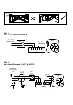
1. Select and follow the appropriate wiring diagram (Fig. 2 & 3).
2. Check all connections have been made correctly and ensure all terminal connections and
cable clamps are securely fastened.
3. Ensure the impeller rotates and is free from obstructions.
C. SETUP
WARNING: THE FAN AND ANCILLARY CONTROL EQUIPMENT MUST BE ISOLATED
FROM THE POWER SUPPLY DURING THE INSTALLATION / OR MAINTENANCE.
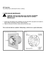
ACCESSING THE CONTROL SETTINGS – (Fig. 4)
1.
Loosen the screw in the bottom of the grille and remove the front grille.
2.
Carefully pull the inner cap from the centre of the fan away from the chassis.
3.
Adjust the settings as outlined below.
SPEED SETTING:
BEFORE SETTING THE SPEED, SWITCH OFF THE MAINS SUPPLY. SPEED SHOULD ONLY BE
SET BEFORE OR DURING INSTALLATION.
The fan has two speed settings for different installation requirements:
1) High
speed:
100SVT and 100SVH models: Dip switch 2 in
the ‘OFF’ position. (
Fig.5 – and right)
100SVB model: Remove jumper. (
Fig.5)
2)
Low speed (Factory set):
100SVT and 100SVH models: Dip switch 2
should be in the ‘ON’ position. (
Fig.5 – and right)
100SVB model: Replace jumper. (
Fig.5)
Dip switch 1 should be in the ‘OFF’ position (100SVT and 100SVH models
only).
1 2
ON
High speed (T & H)
1 2
ON
Low speed (T & H)