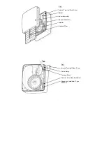
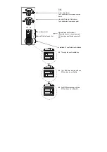
Vent-Axia Lo-Carbon Quadra SELV Series Скачать руководство пользователя страница 9


60

30

15

12

9

6


Fig.7. 
 
Timer adjustment. 
Turn clockwise to increase overrun 
timer. 
 
Humidity Setpoint Adjustment. 
Turn clockwise to raise set point. 


Speed Selection Switches.  
(Example shown is boost speed of 
15 l/s and normal/trickle speed of 6 
l/s.) 


Installation Type Selection Switches: 


  Through the wall installation. 


  1.5m Ø100mm ducting with one 

90° bend and a wall grille. 


  3m Ø100mm ducting with two 

90° bends and a wall grille. 

Boost Speed (l/s) 

Normal/Trickle Speed (l/s) 

Off    On 

Содержание Lo-Carbon Quadra SELV Series

Страница 1: ...Instructions PLEASE READ INSTRUCTIONS IN CONJUNCTION WITH ILLUSTRATIONS PLEASE SAVE THESE INSTRUCTIONS Lo Carbon Quadra SELV IPX7 Safety Extra Low Voltage Stock Ref N Quadra SVTP 442865 Quadra SVHTP 4...

Страница 2: ...hin reach of a person using a fixed bath or shower i e in a nearby wall However the fan must not be placed where it could be submerged in water or regularly exposed to direct water spray e g from a sh...

Страница 3: ...installed and that the optional Filter fig 3 could be removed for cleaning The cardboard fitment in the packaging can be used as a template 3 Set up the appropriate speed selection and other features...

Страница 4: ...and the flange for the thickness of the panel so that the clips can spring open behind the panel 5 Set up the appropriate speed selection and other features as outlined in Section B SETUP 6 Remove th...

Страница 5: ...r RH ii To RAISE the Set Point turn the Humidity Adjuster figs 4 7 CLOCKWISE This makes the fan less sensitive to RH i e the fan will come on at a higher RH C WIRING WARNING THE FAN AND ANCILLARY CONT...

Страница 6: ...embly and Impeller in warm soapy water if they are dirty Do not use abrasive cleaners Dry the parts before replacing them 7 Turn the power to the Fan back on The fan has sealed for life bearings which...

Страница 7: ...Terminal Block Cover Spigot Cover Assembly Chassis Assembly Impeller Optional Filter Fig 4 Internal Terminal Block Cover Cable Clamp Terminal Block Timer and Humidity Adjustment Speed and Installation...

Страница 8: ...Fig 5 Frame from optional Flush Mount Kit Back Box Fig 6 Panel Clip Screw 4 off Panel Clip 4 off...

Страница 9: ...e set point Speed Selection Switches Example shown is boost speed of 15 l s and normal trickle speed of 6 l s Installation Type Selection Switches Through the wall installation 1 5m 100mm ducting with...

Страница 10: ...Fig 9 Wiring diagram without LS connection Fig 10 Wiring diagram with LS connection N Ls 0V Fan Controller LS L N SELV Supply 24V DC 3A UK 24V LS 24V 0V N Ls 0V Fan Controller LS L N SELV Supply 24V...

Страница 11: ...l Factor CTRL 0 65 0 65 0 65 Control Typology Clock Control Local Demand ControlLocal Demand Control Declared Max Internal External Leakage Rates for BVUs or carry over for regenerative heat exchanger...

Страница 12: ...e repaired or at the Company s option replaced without charge provided that the product Has been installed and used in accordance with the instructions given with each unit Has not been connected to a...

Отзывы: