


Page 6 of 12
B)
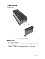
Installing the Controller
Controller Dimensions
Dimensions of the Controller Box
Installing the Controller
1.
Remove the controller from the packaging.
2.
After noting the positions of the cable connections on the unit, select a suitable installation site (allow for an extra 30mm
clearance either end for cable glands. Note that the unit can be ceiling or floor mounted. The site selected must allow
sufficient space around the unit for the removal of the cover after mounting and close enough to be able to be connected
to the fan unit via the 8-core cable.
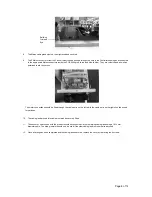
3.
The controller can be mounted using the 4 holes on the flange of the controller housing and appropriate screws.