


PRODUCT DESCRIPTION
The HR100S is a surface mounting heat recovery ventilation unit for use in bathrooms and toilets. It
is designed for mounting on an external wall having a thickness from 100 to 400mm.
The units twin impeller and heat recovery arrangement simultaneously supplies and extracts air
while transferring heat from the stale exhaust airflow to the fresh intake airflow. This providesup to
60% heat recovery from the stale air.
Separation of the exhaust airflow and the intake airflow is maintained through the unit and the
special duct supplied with it.
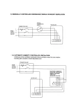
The unit incorporates electrical connections for operating at two speeds, thereby providing trickle
and/or boost ventilation options (see Fig.5).
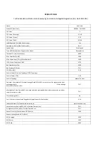
The overall electrical power consumption of the unit is 35 watts at high speed and 15 watts at low
speed. The units motor is fitted with standard thermal overload protection protection, which in the
event of a fault causing the motor to overheat will cut of the electrical supply to the motor.
The fan unit may be connected through a vent-axia ecotronic humidistat (Stock Ref. 563532) or
Ambient Response Humidistat (Stock Ref.563550), which automatically switch the fan unit from
trickle to boost ventilation when the relative humidity in the room exceeds a pre-set adjustable level.
CABLE RUNS
Decide where to site the ventilation unit and work out the cable runs. When using surface wiring
which is not contained in conduit, the wiring must be securely anchored to the mounting surface.
Install the cable runs in conjunction with a fused and switched connection unit located in the vicinity
of where the ventilation unit will be sited. Ensure that the cables for the ventilation unit extend at
least 400mm from the mounting surface.
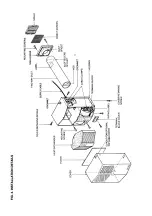
FITTING INSTRUCTIONS (SEE FIG.4)
1. Remove the duct, grille assembly and heat recovery ventilation unit from the packaging.
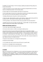
2. After noting the positions of the duct spigot and optional cable entry grommets on the top and
rear of the housing (see Fig. 1). cut a 114mm diameter hole through the wall.
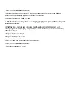
3. Cut the duct to a length which will provide for a flush finish with the internal and external wall
faces. DO NOT CUT THE END OF THE DUCT WHICH IS SLOTTED TO ACCEPT THE
EXTERNAL GRILLE SPIGOT.
4. With the web in the duct vertical, the slotted end of the duct to the outside and the duct
sloping slightly downwards to the outside for drainage of condensation, fix the duct in the wall by
applying suitable gap filler between the duct and hole. The filler must create a flush finish at the
outer wall face to allow the external grille to be fixed satisfactorily. At the inner wall face the filler
must be recessed at least 20mm to allow the duct spigot, on the back of the housing, to locate over
the duct (see Fig.2).
5. Remove the cover from the unit after removing the two retaining screws in the side and
slackening the two retaining screws in the bottom of the cover.


