


4
SURFACE MOUNTING
(PANEL/CEILING)
1.
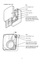
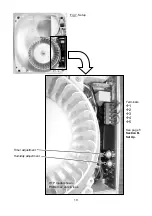
Remove the Front Cover Assembly by slackening the two screws by two turns (
fig.2.)
Lift the
front assembly away from the bottom edge first, then the top edge
.
2. Cut
a
∅
105mm hole, then suitable screw holes in the panel, ensuring that there is sufficient
space for the product to be installed and that the filter (sold separately for the Centrif Duo
Plus) can be removed for maintenance. Either the cardboard fitment or the fan chassis can
be used as a template. The Spigot can be removed temporarily to make it easier. (
Fig 1 & 3
).
3.
Set-up the appropriate speed selection and other features as outlined in
Section B SETUP.
4.
Remove the small Terminal Block Cover in the top right corner (
fig 3
).
5.
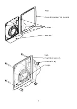
Attach the ducting to the Spigot and locate the fan into the hole in the panel. Feed the wiring
through the hole in the Chassis next to the Terminal Block as you do so.
(fig. 4)
6.
Secure into position using appropriate fixtures.
7.
Select and follow the appropriate wiring diagram in
Section C WIRING.
8.
Replace the little Terminal Block Cover over the Terminal Block (
fig.4
).
9.
Ensure the Impeller rotates freely (
fig.3
).
10. Replace the Front Cover Assembly and tighten the two screws (
fig.2.)
.
11. Make sure that all covers are on correctly to ensure the optimum performance and water
ingress protection of the fan.
12. Switch the mains power supply on and check the fan is operating correctly.
SURFACE MOUNTING
(WALL)
For through-the-wall installations, a Wall Kit (25 41 02 White / 25 41 00 Brown) can be used.
1.
Remove the Front Cover Assembly by slackening the two screws by two turns (
fig.2.)
Lift the
Front Cover Assembly away from the bottom edge first, then the top edge.
2. Cut
a
∅
115mm hole through the wall, ensuring that there is sufficient space for the product to
be installed and that the Filter (
fig.3
) can be removed for maintenance.
3.
Insert the wall sleeve with the larger diameter sleeve on the room-side and cement the ends
into position flush with the wall faces. The wall sleeve should be angled downwards, away
from the fan, to allow any condensation to drain to the outside.
4.
Outside Grille: Using the Grille’s back plate as a template, mark the fixing hole centres on the
wall. Drill and plug the wall and fix the Grille into position. Ensure the louvres are pointing
downwards.
5.
Set-up the appropriate speed selection and other features as outlined in
Section B SETUP.
6.
Remove the little Terminal Block Cover in the top right corner (
fig 3
).
7.
Using the fan chassis as a template, carefully sliding the Spigot into the Wall Liner, mark the
fixing hole centres on the wall. Alternatively, the cardboard fitment can be used as a
template.
8.
Drill and plug the wall using the fixings provided.
9.
Feed the wiring through the hole near the Terminal Block and secure the fan into position
using the screws provided.
10. Select and follow the appropriate wiring diagram in
Section C WIRING.
11. Replace the Terminal Block Cover (
fig.4
).
12. Ensure the Impeller (
fig.3
) rotates freely.
13. Replace the Front Cover Assembly and tighten the two screws (
fig.2
).
14. Make sure that all covers are on correctly to ensure the optimum performance and water
ingress protection of the fan.
15. Switch the mains power supply on and check the fan is operating correctly.
FLUSH MOUNTING (PANEL/CEILING)
A Flush Mount Kit (439256) is required.
1.
Remove the Front Cover Assembly by slackening two screws by two turns (
fig.2).
Lift the
front assembly slowly from the bottom edge first, then the top edge.
2.
Mark and cut a rectangular hole 222mm (w) x 253mm (h) through the panel ensuring that
there is sufficient space for the product to be installed and that the Filter (
fig.3
) can be
Содержание Centrif Duo DP 25 63 20C
Страница 11: ...11 Fig 8 Siting of the fan 3 2 ...