


1. TYPICAL INSTALLATIONS
(CONT’D)
VH0043
- 5 -
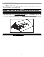
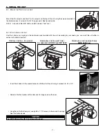
1.1.3 R
ETURN
-
TO
-R
ETURN
I
NSTALLATION
(C
ONNECTION TO A FORCED AIR SYSTEM
)
1.1 HRV 2500, HR 2.5, HEPA 3000, HF 3.0
AND
HEPA 4000 U
NIT
I
NSTALLATIONS
(
CONT
’
D
)
Do not connect the unit (HRV 2500, HR 2.5,
HEPA 3000, HF 3.0 or HEPA 4000) to any forced
air system supply duct.
CAUTION
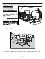
The HEPA 4000 unit was created to meet specific requirements related to geographic locations. Take a look at the map below.
This unit can be installed anywhere in the USA, but the ventilation will be reduced in cold weather. HEPA filtration is not affected however.
NOTE:The HEPA 4000 unit is designed to assist in the management of humidity introduced into the home. In extreme humidity
conditions, the use of additional dehumidification may be required to quickly remove all excess moisture.
HELENA
OLYMPIA
SALEM
BOISE
BISMARCK
SALT LAKE CITY
ST. PAUL
DES MOINES
MADISON
HARRISBURG
SACRAMENTO
DENVER
TOPEKA
DETROIT
INDIANAPOLIS
SANTA FE
SPRINGFIELD
OKLAHOMA CITY
PHOENIX
COLUMBUS
NASHVILLE
ATLANTA
BATON ROUGE
AUSTIN
COLUMBIA
RALEIGH
WASHINGTON
HARTFORD
BOSTON
RENO
HEPA 4000 RECOMMENDED AREA
VN0005A
In this area, the HEPA 4000 unit may be used, but below -8
°
C (16
°
F),
the duration time of ventilation will be reduced.
1.2 I
NSTALLATION FOR
HEPA 4000 O
NLY
1.2.1 G
EOGRAPHICAL
L
OCATION
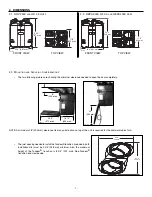
HRV 2500
AND
HR 2.5
UNITS ONLY
Stale air is exhausted to the outside. Outside fresh
air is filtered and supplied to the return (plenum) of
the forced air unit. See figure at right.
HEPA 3000, HF 3.0
AND
HEPA 4000
UNITS ONLY
A portion of stale air is exhausted to the outside
and the rest is drawn to the unit. Outside fresh air is
blended with interior air and then filtered. This filtered
air is supplied to the return (plenum) of the forced
air unit. See figure at right.
A
LL UNITS
:
To avoid cross-contamination and achieve the highest
efficiencies, the forced air system blower must
always be ON.
NOTE: Home with multiple forced air systems
should have 1 unit on each system.


