To adapt the appliance to a gas different from that
for which it was set up (see gas type label inside
the warming compartment door) proceed as follows:
remove the grids
remove the burners caps and burner heads
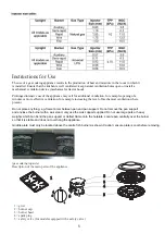
with a 7 mm socket spanner unscrew and remove the injectors.
replace the injectors with those supplied corresponding to the
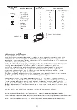
gas available (see burner and injector characteristics Table)
replace the various parts proceeding in reverse.
The flame on the small output is regulated by the factory.
the minimum flame again. The operations necessary to set
the minimum flame are as following:
light the burner ;
turn the knob to the minimum position ;
take out the knob (and gasket if there is one) ;
l
l
l
l
l
l
l
l
7
correct method of operation. In case the appliance fails to operate correctly after all checks have been carried
out, refer to the authorised service provider in your area.
When satisfied with the operation of the cooker, please instruct the user on the
LPG
When converting from Natural Gas to
ensure that the NG regulator is removed and replaced with the Test
Point Adaptor. A gas regulator suitable for a supply pressure of should be part of the gas cylinder supply and the
appliance test point pressure must be 2.75 kPa
it may be necessary to regulate
When the injectors have been replaced,
SETTING THE MINIMUM FLAME
THE BURNERS REQUIRE NO REGULATION OF THE PRIMARY AIR.
ABNORMAL OPERATION
ANY OF THE FOLLOWING ARE CONSIDERED TO BE ABNORMAL OPERATION
AND MAY REQUIRE SERVICING:
Y
l
ellow tipping of the hob burner flame.
l
Sooting up of cooking utensils.
l
Burners not igniting properly.
l
Burners failing to remain alight.
l
Burners extinguished by oven door.
l
Gas valves, which are difficult to turn.
IN CASE THE APPLIANCE FAILS TO OPERATE CORRECTLY, CONTACT
THE AUTHORISED SERVICE PROVIDER IN YOUR AREA.
l
put the knob back on and turn it quickly from the maximum position to the minimum position, checking
that the flame does not go out ;
l
for burners with safety valve make sure that the regulation obtained is sufficient to maintain heating of
the thermocouple. If it is not, increase the minimum
l
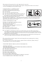
LPG TO NG:Use a thin blade screwdriver to turn the by-pass screw located above left of the gas
valve,shaft as shown right. Turn gently the by-pass screw clockwise to the end completely then turn it
anti-clockwise 1 turn for the Triple ring,7/8 turn for the Fish,3/4 turn for the Rapid,1/2 turn for the Semi-
Rapid and 3/8 turn for the Auxiliary .
l
NG TO LPG: Use a thin blade screwdriver to turn the by-pass screw located above left of the gas valve
shaft as shown right.Turn gently the by-pass screw clockwise to the end.
Содержание VU90EG
Страница 1: ...venini com au user manual 2 year warranty VU90EG 90cm freestanding cooker...
Страница 13: ...3 12 TIMER...
Страница 18: ...venini com au...


