


8 VELUX
®
VELUX
®
9
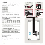
6 pole DIP switch
Various wind and rain parameters and operating modes can be set by
means of the integrated 6 pole DIP switch.
Once the sensor is installed and operational, the DIP switches
should be set to the settings as shown below:
Switch 1
OFF
Switch 2
OFF
Switch 3
ON
Switch 4
ON
Switch 5
OFF
Switch 6
OFF
IMPORTANT:
Factory setting = Test setting.
Note:
In the test setting, activation and drop out delay is deactivated!
If the red light-emitting diode in the sensor is lit, the sensor has been
activated by wind and/or rain and the modular skylight closes.
Other settings are possible. It is, however, not advisable to use the
10 m/s, 12 m/s or 14 m/s wind speed settings as there is the risk of dam-
age to fittings before the modular skylight can close fully. These settings
are used at your own discretion.
DIP switch settings for wind speed
Test
Approx
3 m/s
Approx
4 m/s
Approx
6 m/s
Approx
8 m/s
Approx
10 m/s
Approx
12 m/s
Approx
14 m/s
Switch 1
OFF
ON
OFF
ON
OFF
ON
OFF
ON
Switch 2
OFF
OFF
ON
ON
OFF
OFF
ON
ON
Switch 3
OFF
OFF
OFF
OFF
ON
ON
ON
ON
DIP switch setting for wind activation delay
2 seconds
5 seconds
Switch 4
OFF
ON
DIP switch setting for wind/rain drop out delay
10 minutes
20 minutes
Switch 5
OFF
ON
DIP switch setting for monitoring (not supported by the system)
Switch 6
OFF
ON
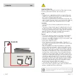
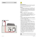
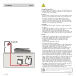
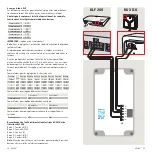
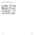
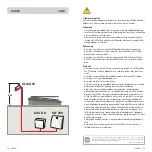
Connection to power supply unit KUX 110 and interface KLF 200
Terminal 1: Supply voltage AC/DC
Terminal 2: Supply voltage AC/DC
Terminal 3: Relay (C)
Terminal 4: Relay (N/C contact)
Terminal 5: Relay (N/O contact)
Note:
Please refer to the instructions for these products that are for
indoor installation only.
ON OFF
1 2 3 4 5
6
1
2
3
4
5
6
A
4 5
3
2
1
B
9 10
8
7
6
17 18 19
− +
Reset
Central unit
6
5
4
3
2
1
1
6
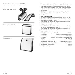
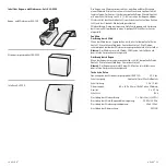
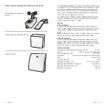
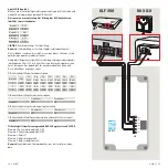
For assembly, remove plug connection from the cover.
Do not mismate during assembly.
LED
on
Terminal 1 = Supply voltage AC/DC
= Relay (arm)
(N/C contact)
6 is internally connected to terminal 2.
Terminal 2 = Supply voltage AC/DC
Terminal 3
Terminal 4 = Relay
Terminal 5 = Relay (N/O contact)
Terminal
1
2
3
4
5
6
AC/DC AC/DC
off
1
2
3
4
5
6
AC/DC
AC/DC
Connection (DIP switch 6 = off)
Switching
contact (N/O)
Supply
voltage
Central unit
1
2
3
4
5
6
AC/DC
AC/DC
Connection (DIP switch 6 = on)
automatic trip in the event of a supply voltage failure
Supply
voltage
Switching
contact (N/C)
”Closes when wind and/or rain“
”Opens when wind, rain and/or supply voltage failure“
+
−
A B C D E
1 2 3 4 5 6 7
8 9 10
A B C D E
1 2 3 4 5 6 7
8 9 10
ETHERNET
ETHERNET
RESET
RESET
USB
USB
A B C D E
1 2 3 4
5 6 7 8 9 10
A B C D E
1 2 3 4
5 6 7 8 9 10
ETHERNET
ETHERNET
RESET
RESET
USB
USB
KLF 200
KUX 110


