1
.
w w w . v e l o d y n e . c o m
MicroVee User’s Manual
i
Caution
IMPORTANT SAFETY INSTRUCTIONS
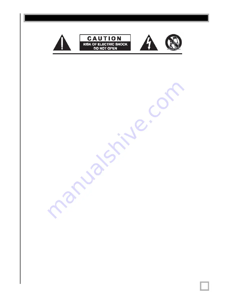
Caution
To reduce the risk of electric shock, do not remove cover (or back). No user-serviceable parts inside. Refer
servicing to qualified service personnel.
The lightning flash with arrowhead symbol is intended to alert the user to the presence of uninsulated
“dangerous voltage” within the product’s enclosure that may be of sufficient magnitude to constitute a risk
of electric shock to persons.
The exclamation point symbol is intended to alert the user to the presence of important operating and
maintenance (servicing) instructions in the literature accompanying the subwoofer.
1.
Read Instructions —
All safety and operating instructions should be read before the product is operated.
2.
Retain Instructions —
The safety and operating instructions should be retained for future reference.
3.
Heed Warnings —
All warnings on the product and in the operating instructions should be
adhered to.
4.
Follow Instructions —
All operating and use instructions should be followed.
5.
Water and Moisture —
The product should not be used near water — for example, near a bathtub,
washbowl, kitchen sink, laundry tub, in a wet basement, near a swimming pool or the like.
6.
Carts and Stands —
The product should be used only with a cart or stand recommended by
the manufacturer.
7.
Wall or Ceiling Mounting —
The product should be mounted to a wall or ceiling only as recommended
by the manufacturer.
8.
Ventilation —
The product should be situated so that its location or position does not interfere with its
proper ventilation. For example, the product should not be situated on a bed, sofa, rug, or similar surface
that may block the ventilation openings; or placed in a built-in installation such as a bookcase or cabinet
that may impede the flow of air through the ventilation openings.
9.
Heat —
The product should be situated away from heat sources such as radiators, heat registers,
stoves, or other products that produce heat.
10.
Power Sources —
The product should be connected to a power supply only of the type described in
the operating instructions or as marked on the product.
11.
Grounding or Polarization —
This product may be equipped with a polarized alternating-current line plug
(a plug having one blade wider than the other). This plug will fit into the power outlet only one way.
This is a safety feature. If you are unable to insert the plug fully into the outlet, try reversing the plug.
If the plug should still fail to fit, contact your electrician to replace your obsolete outlet. Do not defeat
the safety purpose of the polarized plug.
12.
Power-Cord Protection —
Power-supply cords should be routed so that they are not likely to be walked
on or pinched by items placed upon or against them, paying particular attention to cords at plugs,
convenience receptacles, and the point at which they exit from the product.
13.
Cleaning —
The product should be cleaned only as recommended by the manufacturer.
14.
Nonuse Periods —
The power cord of the product should be unplugged from the outlet when left unused
for a long period of time.
15.
Object and Liquid Entry —
Care should be taken so that objects do not fall and liquids are not spilled
onto the enclosure.
16.
Damage Requiring Service —
The product should be serviced by qualified service personnel when:
a. The power-supply cord or plug has been damaged.
b. Objects have fallen or liquid has been spilled into the product.
c. The product has been exposed to rain.
d. The product does not appear to operate normally or exhibits a marked change in performance.
e. The product has been dropped or damaged.
17.
Servicing —
The user should not attempt to service the product beyond what is described in the
operating instructions. All other servicing should be referred to qualified service personnel.
18.
Lightning —
For added protection for the product during a lightning storm or when it is left unattended
and unused for long periods of time, unplug it from the wall outlet.
19.
Overloading —
Do not overload wall outlets, extension cords or integral convenience receptacles as this
can result in a risk of fire or electric shock.
20.
Attachments —
Only use attachments and accessories specified by the manufacturer.
21.
Voltage —
Insure that the subwoofer is only connected to the rated source voltage. Do not connect the
120-volt version to 230-volts or vice-versa. This will result in damage to the subwoofer and possible
injury to the user.
CAUTION:
To prevent electrical shock, match wide blade of plug to wide slot, fully inserted.


