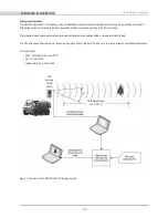


This section describes the standard set up assuming you are connecting the sensor to a standard computer or laptop and mounting the
sensor on a vehicle. For other connections and mounting locations, please contact Velodyne for technical assistance.
The standard setup involves:
1. Unpacking the shipping case contents.
2. Securely mounting the sensor base to a vehicle or other scanning platform.
3. Connecting power to the sensor.
4. Connecting the sensor’s data output to the computer.
Case Contents
The shipping case contains:
• HDL-32E sensor unit with approximately 3 meter cable terminated at an interface box.
• Desktop AC/DC power adapter.
• AC cord.
• 4.5 meter Ethernet cable.
• Garmin GPS-18LV GPS receiver with 5 meter cable.
• CD with:
- User manual. Check www.velodynelidar.com for updates.
- Calibration file (db.xml)
- DSR Viewer software
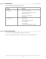
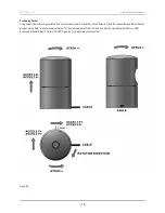
Mount Base
The sensor base provides mounting holes on the base. The sensor can be mounted at any angle from 0° to 360° with respect to the
sensor base.
Refer to the figure below for location of the four 10-32 threaded, 3/8” deep mounting holes.
Figure 2: Sensor Base Mounting
[ 3 ]
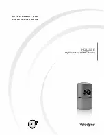
HDL-32E User’s Manual
setuP
144.2
5.68
OVERALL HEIGHT
3.36
85.3
MOUNTING HOLES
FOUR 10-32 THREADED
3/8” DEEP
INTERFACE CABLE
3 METERS LONG
2.033
51.6
2.033
51.6
TWO .156 LOCATING FEATURES
FOR 5.32” DOWELL PINS
2.876
73.1