- 6 -
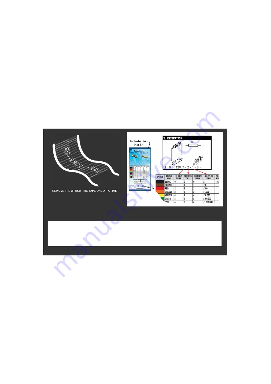
DO NOT BLINDLY FOLLOW THE ORDER OF THE
COMPONENTS ONTO THE TAPE. ALWAYS CHECK THEIR
VALUE ON THE PARTS LIST!
Страница 1: ...RA STRA STRA STRA STRA A A STRA STR T T TED TED TED TED TED TED TED TED TED TED TED ED TED ASS ASS AS S ASS ASS ASS ASSE ASSE ASSE ASSE ASS ASSE ASSE ASSE ASSE ASSE SE EMBLY MBLY MBL BLY BLY BLY BLY B...
Страница 2: ...Forum Forum Participate our Velleman Projects Forum Subscribing our newsletter visit www vellemanprojects eu...
Страница 3: ...750mA continuous 1A peak wide range AC power input 5 30V 5 dry contact inputs 1 logic open collector output power supply 10 30VAC dimensions 117 x 65 5 x 25mm 4 6 x 2 58 x 0 98 With the K8096 1 chann...
Страница 4: ...xample operate a red led 1 7V on a 9Vdc source Required led current for full brightness 5mA this can be found in the datasheet of the led LEDs in series Example 3 x red led 1 7V on 9V battery Required...
Страница 5: ...rs A basic range is ne For some projects a basic multi meter is required or might be handy 1 2 Assembly Hints Make sure the skill level matches your experience to avoid disappointments Follow the inst...
Страница 6: ...6 DO NOT BLINDLY FOLLOW THE ORDER OF THE COMPONENTS ONTO THE TAPE ALWAYS CHECK THEIR VALUE ON THE PARTS LIST...
Страница 7: ...820pF 82 C15 820pF 82 C16 820pF 82 C17 820pF 82 Vertical diodes 8 7 1 IC socket 5 Watch the popsition of the notch Watch the popsition of the notch SK2 R D CATHODE D4 D7 1N4007 Watch the polarity Wat...
Страница 8: ...SK10 3p OUT Terminal Block Quartz crystal 13 14 SK1 2p AC power 10 30V Electrolytic capacitors 12 IC 17 Watch the position Watch the position of the notch of the notch IC1 VK8096 programmed PIC18F14K...
Страница 9: ...manprojects eu Step 1 Download the software on our website or via the QR code Step 2 open the le en select the software Step 3 Select next to begin the installation procedure Step 4 Select the destina...
Страница 10: ...10 Software installtion Step 7 Select install for installing the software Step 8 Select the additional tasks you would like then click next Step 9 Click nish to exit setup...
Страница 11: ...Motor Card onto the PC rst Step 1 Select speci c location Step 2 Choose the desired location on your hard drive the default location is C Program Files Velleman stepper motor cards Step 3 Click Contin...
Страница 12: ...12 Connection diagram 0 30V AC ex alert switch ex limit switch INPUT 1 open collector output OUT 21 CONNECTION DIAGRAM OUT external power supply Min 5V Max 30V ex optional stepping motor MOTS3...
Страница 13: ...can connect to the card when Card type and Port are lled in Steps Fill in the number of steps the motor needs to execute Speed This indicated the time between each step A larger number results in a sl...
Страница 14: ...14 PCB...
Страница 15: ...T U O 5 1 3 T U O 4 1 4 T U O 3 1 5 T U O 2 1 6 T U O 1 1 7 T U O 0 1 D M O C 9 D N G 8 A 3 0 0 2 N L U 3 C I D N G 1 2 3 0 1 K S K 0 1 3 R c i p V 5 1 2 6 K S 1 2 5 K S 1 2 7 K S 1 2 9 K S 1 2 8 K S...
Страница 16: ...man Projects catalogue is now available Download your copy here www vellemanprojects eu Modi cations and typographical errors reserved Velleman nv H8096 IP Velleman NV Legen Heirweg 33 9890 Gavere 5 4...