background image

17 

'I' 


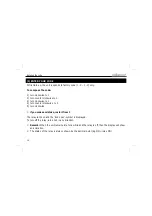
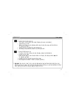
Relay turns on at power up


You have 1 min to enter your code (Display shows an animation) 


Compose your code 
If the correct code is not entered within one minute, the relay will turn off and 
'A'  (alarm) will flash. 


Release the menu button to select this mode


Decimal point will flash 3 times to confirm selection


Menu options 


Remark: 

The modes ‘|’ and ‘o’ can only be changed during the first minute after power up. 

Otherwise, the unit will go into alarm-mode and access to the menu will be prohibited. In that 
case, briefly interrupt the power supply to restart the unit. 

'o' 


Relay is off at power up.   
You have 1 min to enter your code. (Display shows an animation) 


Compose your code 
If the correct code is not entered within one minute, the relay will turn 

on

 and 

'A'  (alarm) will flash.   


Release the menu button to select this mode.     


Decimal point will flash 3 times to confirm selection


Содержание K8082

Страница 1: ... Safe style code lock K8082 ILLUSTRATED ASSEMBLY MANUAL H8082IP 1 Total solder points 117 Difficulty level beginner 1 2 3 4 5 advanced Novelty code lock ...

Страница 2: ...tion application examples open a door gate fence arm disarm your alarm system prevent unauthorized use mode 3 of car entertainment systems computers machinery Specifications relay output NO NC 3A 24VDC max power supply 12VDC 100mA max Dimensions front 85 x 85mm 3 35 x 3 35 mounting depht 45mm 1 77 Features Specifications ...

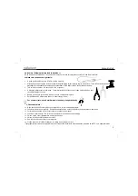
Страница 3: ...the eyes Needle nose pliers for bending leads or to hold components in place Small blade and Phillips screwdrivers A basic range is fine For some projects a basic multi meter is required or might be handy 1 2 Assembly Hints Make sure the skill level matches your experience to avoid disappointments Follow the instructions carefully Read and understand the entire step before you perform each operati...

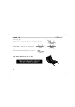
Страница 4: ...st the PCB surface and carefully solder the leads 2 Make sure the solder joints are cone shaped and shiny 3 Trim excess leads as close as possible to the solder joint REMOVE THEM FROM THE TAPE ONE AT A TIME AXIAL COMPONENTS ARE TAPED IN THE CORRECT MOUNTING SEQUENCE ...

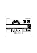
Страница 5: ... C1 C2 C5 C6 D1 D2 IC1 RY1 SK1 SK4 SW1 T1 VR1 1 C1 C2 COM NO NC Break the PCB into two pieces 2 1 g f e d b a 5V gnd SET NO COM NC 12VDC Velleman P8082 1 24V 3A max C4 C3 R5 R4 R3 R2 R1 C7 C1 C2 C5 C6 D1 D2 IC1 RY1 SK1 SK4 SW1 T1 VR1 1 C1 C2 COM NO NC Setup Velleman 1m timer 1 o 1m timer 0 d default S set code c cont t timer cw ccw 0 cw 1 ccw 0 cw 1 code default f g e d c b a enc2 enc1 5V 2 1 g f ...

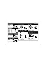
Страница 6: ...ty C RY1 VR15M121C 10 Relay RY IC1 VK8082 programmed PIC16F630 I P 11 IC watch the position of the notch VR1 UA78L05 7 Voltage regulator VR SK1 2p SK2 3p 8 Terminal blocks T1 BC547 6 Transistor T C1 100nF 104 C2 100nF 104 C3 100nF 104 C4 100nF 104 C5 100nF 104 5 Capacitors SW1 SET 4 Push button ...

Страница 7: ...c b a 5V gnd P8082 1 R13 R12 R11 R10 R9 R8 R7 R6 DY1 SW2 1 Mount the components on the display PCB R6 560 5 6 1 B R7 560 5 6 1 B R8 560 5 6 1 B R9 560 5 6 1 B R10 560 5 6 1 B R11 560 5 6 1 B R12 560 5 6 1 B R13 560 5 6 1 B 1 Resistors R Pay attention to the position of the decimal point DY1 2 Display SW2 Rotary encoder 3 Digital potentiometer Construction main PCB ...

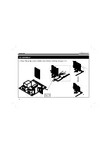
Страница 8: ...8 Assembly Mount the jump wires onto the main PCB according to figure 1 0 3 ASSEMBLY Fig 1 0 ...

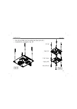
Страница 9: ...9 Assembly Mount 4 print tabs onto the display print see figure 2 0 Assemble the unit together fig 3 0 Fig 2 0 M3 Nut 10mm spacer 20mm M3 bolt Main PCB Display PCB Fig 3 0 ...

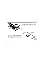
Страница 10: ...int and solder them see figure 4 0 Assembly Fig 4 0 Main PCB Display PCB red display filter adhesive tape Fig 5 0 Mount the red display filter onto the front panel backside Fix the red display filter using a piece of trans parent adhesive tape four sides fig 5 0 ...

Страница 11: ...11 Assembly Place the unit onto the front panel fig 6 0 Fasten the potentiometer Slide the black plastic knob on the axe and fasten the unit fig 7 0 Fig 7 0 Fig 6 0 ...

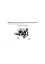
Страница 12: ...12 Carefully solder the 4 PCB pins to the front panel Watch the position of the display Fig 8 0 Assembly ...

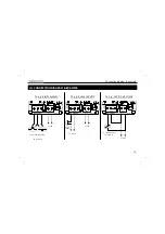
Страница 13: ...R2 C7 C1 D1 RY1 SK1 SK4 VR1 NO NC 12VDC to e g alarm system 3A 24V max To e g buzzer 24VDC To e g 12VDC door lock NO COM NC 12VDC 24V 3A max C4 R2 C7 C1 D1 RY1 SK1 SK4 VR1 NO NC NO COM NC 12VDC 24V 3A max C4 R2 C7 C1 D1 RY1 SK1 SK4 VR1 NO NC 12VDC e g 24VDC e g buzzer 24VDC 12VDC e g 12VDC doorlock 3A 24V max ...

Страница 14: ...ockwise to 1 4 turn counter clockwise to 0 5 turn clockwise if you make a mistake restart from 1 The relay turns on and the lock open symbol is displayed To turn off the relay turn knob in any direction Remark When the unit remains idle for a while and the relay is off then the display will show an animation The status of the relay is always shown by the decimal point dp ON relay ON ...

Страница 15: ...times to confirm you left the menu If the unit was set to timer mode the display will flash the current set time Turn knob in any direction to select a menu item while still holding the button 6 MENU OPTIONS t timer mode The output relay generates a timed pulse between 0 5 and 9s To set timer mode Release button Set required time 0 9s 0 0 5s Hold button Select t Release button Display will flash s...

Страница 16: ...ect set mode Release the menu button Compose your custom 4 digit code change direction after each digit and last digit The decimal point will flash 3 times to indicate that your code has been stored Remark If the unit remains idle for a while the unit will return to normal operation and the code will not be changed d default Return to the factory code 1010 To set default mode Release the menu butt...

Страница 17: ...The modes and o can only be changed during the first minute after power up Otherwise the unit will go into alarm mode and access to the menu will be prohibited In that case briefly interrupt the power supply to restart the unit o Relay is off at power up You have 1 min to enter your code Display shows an animation Compose your code If the correct code is not entered within one minute the relay wil...

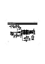
Страница 18: ...18 6 Schematic diagram Schematic diagram ...

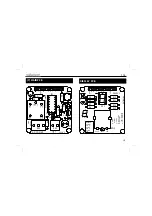
Страница 19: ...R4 R3 R2 R1 C7 C1 C2 C5 C6 D1 D2 IC1 RY1 SK1 SK4 SW1 T1 VR1 1 C1 C2 COM NO NC Setup Velleman 1m timer 1 o 1m timer 0 d default S set code c cont t timer cw ccw 0 cw 1 ccw 0 cw 1 code default f g e d c b a enc2 enc1 5V 2 1 g f e d c b a 5V gnd P8082 1 R13 R12 R11 R10 R9 R8 R7 R6 DY1 SW2 1 DISPLAY PCB ...

Страница 20: ...ns and typographical errors reserved Velleman Components nv H8082IP 1 2006 rev 1 0 VELLEMAN Components NV Legen Heirweg 33 9890 Gavere Belgium Europe www velleman be www velleman kit com 5 4 1 0 3 2 9 3 6 1 8 1 5 ...

Отзывы: