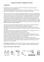
background image

- 2 - 

1.


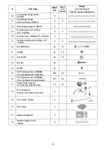
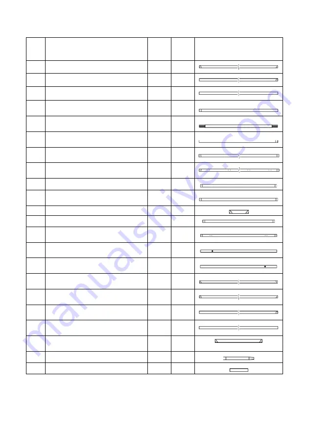
LIST OF ACCESSORIES 


Part name 

BASE 

13’L


INSERT 

+6.5’L


(optional)


Image 

(could be different 

from the actual configuration)


End rafter left, 1400mm 


End rafter right, 1400mm 


End post, side, 1600mm 


End crosspiece, lower side,  
810mm 


End crosspiece, lower central  
910mm (with X-crimping) 


End crosspiece, lower side,  
810mm 


Left door-way post,   
1970mm 


Right door-way post, 
1970mm (with holes for hinge) 


10 

End crosspiece, upper,960mm 


11 

End crosspiece, central lateral,  
810mm 


12 

Jib-stick, small support, 150mm 


15 

Door lintel 

C

”,“

D

,  902mm 


16 

Door post, right, 

C

”,“

D

”, 9

35mm  

(with apertures for door hinges) 


17 

Upper door  post, left,  

C

”, 

935mm 

(aperture for a door handle, lower) 


18 

Lower door post, left,  

D

”, 

935mm 

(aperture for a door handle, upper) 


19 

Door diagonal brace, 

C

”,“

D

”, 


1100mm 


20 

Intermediate arch rafter left,  
1400mm 


21 

Intermediate arch rafter right,  
1400mm 


22 

Side post for intermediate arch,  

E

”,  

1600mm 

10 


23 

Intermediate arch braces 

E

”, 


250mm 

15 


24 

Anchor post, 250mm 

14 


25 

Anchor  grouser, 150mm 

14 


Содержание DAISY

Страница 1: ...CHNICAL MANUAL DAISY Made of 1 x1 Galvanized Steel Pipe Covered with High Density UV Polycarbonate Set of product Width 8 3ft 2 53m Height 7 2ft 2 2m Length of base 13ft 4m Optional Extension 6 5ft 2m etc ...

Страница 2: ...eenhouse should be assembled and installed on the ground according the instruction The buyer should control the assembly quality if it is made by third person Self tapping screws of mount structure should be tightened to contact the flat head of the screw with the covering surface and hold it to the frame but do not allow the extra rundown of the screws Avoid installing the greenhouse closely to t...

Страница 3: ...nge 2 10 End crosspiece upper 960mm 2 11 End crosspiece central lateral 810mm 4 12 Jib stick small support 150mm 8 15 Door lintel C D 902mm 8 16 Door post right C D 935mm with apertures for door hinges 4 17 Upper door post left C 935mm aperture for a door handle lower 2 18 Lower door post left D 935mm aperture for a door handle upper 2 19 Door diagonal brace C D 1100mm 4 20 Intermediate arch rafte...

Страница 4: ...lding 90 1600mm 4 31 Outside roof side drip molding 120 1995mm 4 2 40 Bolt М6х60mm 42 18 41 Nut М6 42 18 42 Washer М6 42 18 43 Bolt М4 32 44 Nut М4 32 45 Self Tapping screw 4 2х16mm for assembling frame elements 388 90 46 Self Tapping screw 4 2х19mm для крепления поликарбоната 220 54 47 Plastic thermo washer for fastening polycarbonate 172 42 48 Door handle set handle cover plate catch lock 4 49 D...

Страница 5: ...e correct geometry assembly must be done on a level and flat surface Before reassembling sort and lay out the end caps doors and intermediate arches parts according to the diagram and the parts list Punching holes for fixing polycarbonate on the details of the ends and doors should be located on one side For convenience and acceleration of assembly fastening of parts with self tapping screws can b...

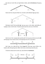
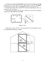
Страница 6: ...lf tapping screws on both sides The distance between the posts must be 910mm 3 3 Connect End crosspiece 4 and 6 with End crosspiece 5 fasten with 45 self tapping screws on both sides 2 self tapping screws for 1 connection 3 4 Fasten the collected item from clause 3 3 Door way posts 3 7 8 at the bottom with self tapping screws 45 on both sides 2 self compound self press The distance between the doo...

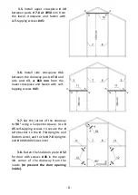
Страница 7: ...rom the lower crosspiece and fasten with self tapping screws 45 3 7 Set the corner of the doorway to 90 using a Carpenter square Use 45 self tapping screws to secure the 12 Jibs stick to the 7 8 Uprights and Bottom Lintel and to the 7 8 Uprights and 11 Middle Side Lintel 3 8 Fasten the Stubborn plate 52 for door with screws 45 in the upper left corner of the doorway from the inside to prevent the ...

Страница 8: ...t and 17 18 with hole for handle must be left Hole for the handle in the top door C should be located below and in the bottom door D from above Insert Carpenters square and make sure it is 90 Insert and fasten the diagonal air gate door support 19 with screws 45 Doors C D 3 10 Insert the doors C D in the opening of the Ends A and B secure with hinge 50 bolts 43 and nuts 44 ...

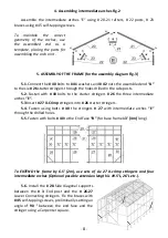
Страница 9: ...h 40 bolts to the starter stringers 26 the three intermediate arches E 5 3 Insert 27 X Crimp stringers into 26 starter stringers 5 4 Fasten using bolts 40 the stringers 27 with intermediate arches E through the drilled holes 5 5 Fasten with bolts 40 to the End Face B for base frame 13 4 m long To EXTEND the frame by 6 5 2m use sets of six 27 X crimp stringers and four intermediate arches Optional ...

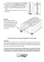
Страница 10: ...ount the leg and screw the self tapping screws back 6 INSTALLATION OF CELLULAR POLYCARBONATE CP TO THE ENDS Important For Polycarbonate positioning it is important that all cellular lines be located in a vertical position downwards Be sure to remove the wrapping film from both sides of the sheet The manufacturer marks the work face sunward of cellular polycarbonate with a certain mark a color bar ...

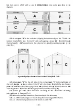
Страница 11: ...6 3 Attach part A to the left side of the end and part C to the right side of the end aligning the lower edge of the CP with the lower lintel of the end Fasten parts A and C with self tapping screws 46 19mm through thermal washers 47 according to the scheme for attaching polycarbonate to the ends Ext 6 4 Fasten part D above the door according to the scheme for attaching polycarbonate to the ends E...

Страница 12: ...andles from kit 48 into the Ø12 holes on the doors after drilling the corresponding holes in the polycarbonate Put on the deadbolt and trim from the back side fix the handle and trim with 45 self tapping screws 6 10 Secure the door latch 51 with 45 self tapping screws from the inside between the lower and upper doors so that the doors can be locked together To do this it will be necessary to unscr...

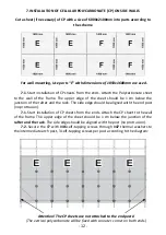
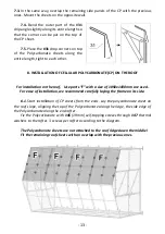
Страница 13: ...d the rack The side edge should be aligned with the end post no protrusion 7 1 Start installation of CP sheets from the ends Attach the CP sheet to the wall of the frame The upper edge of the sheet should be 1 cm below the junction of the rafter and the rack The side edge should be aligned with the post no protrusion 7 2 Secure the CP with 46 self tapping screws through 47 thermal washers to the i...

Страница 14: ...tallation on the roof Use parts F with a size of 1050x1400mm are used For ease of installation we recommend carefully laying the frame on its side 8 1 Start installation of CP sheets from the ends Lay the polycarbonate sheet on the roof slope aligning the top of the Polycarbonate along the ridge the side edge of the Polycarbonate along the end rafter Fix the Polycarbonate with 46 19mm self tapping...

Страница 15: ...four end corners 30 90 100mm using self tapping screws 46 19mm on the vertical corners of the frame 6 self tapping screws per corner closing the corner joints of the polycarbonate sheets 9 3 Fit the remaining corners 29 120 2025mm over the joint between the roof and wall polycarbonate sheets using 46 19mm self tapping screws 29 ...

Страница 16: ...wering the greenhouse into a trench or pits make sure that there is no longitudinal distortion of the frame and no displacement of the tie straps from the arches After tamping the ground make sure that the tie straps are not sideways and are located along the arches Adjust tapes if necessary To strengthen the greenhouse you can use a wooden concrete or brick foundation To prevent moisture from ent...

Страница 17: ...a situation in which harmful insects crawl into a warm greenhouse with the onset of cold weather and in spring they eat young roots and sprouts If it is not possible to dismantle the sheets it is necessary to reinforce the arches from the inside with T shaped wooden supports made of a wooden bar with a cross section of at least 50x50mm placing them inside the greenhouse one bar for each arch Woode...

Страница 18: ...nth period after 1 year of full coverage If the repair is determined to be covered under warranty and it is consumer responsibility to send required evidence as pictures and video of damaged or broken parts 6 The warranty covers delivery cost within 50 mile radius from the store The customer is responsible for freight charges to all further destinations outside of 50 mile radius 7 The warranty cov...

Страница 19: ...under proper usage Due to the continuous improvement of the products the manufacturer reserves the right to make changes in the design without prior notice to the consumer The products are not subject to mandatory certification Distributed by VELCOM INC 847 507 8448 224 254 3993 ...

Отзывы: