Vega VEGAPULS 63 Скачать руководство пользователя страница 12

12

5 Set up with the display and adjustment module

VEGAPULS 63 • HART and accumulator pack

47126-EN-210621

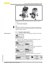
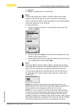
The radar sensor measures the distance from the sensor to the 

medium surface. For indication of the real level, an allocation of the 

measured distance to the percentage height must be carried out.

100%

0%

0,5 

m

(19.68

")

m

(196.

9")

2

1

3

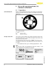
Fig. 6: Parameterisation example, Min./max. adjustment
1  Min. level = max. measuring distance

2  Max. level = min. measuring distance

3  Reference plane

For this adjustment, the distance is entered when the vessel is full 

and nearly empty. If these values are not known, an adjustment with 

other distances, for example, 10 % and 90 % is also possible. Starting 

point for these distance specifications is always the seal surface of 

the thread or flange.

The function " 

Echo curve memory

" makes it possible to save the 

echo curve at the time of setup. This is generally recommended, and 

it is absolutely necessary if you want to use the Asset Management 

functions. If possible, the curve should be saved with a low level in the 

vessel. 

With the adjustment software PACTware and a PC, a high resolution 

echo curve can be displayed and used to recognize signal changes 

during operation. In addition, the echo curve of setup can be dis

-

played in the echo curve window and compared with the current echo 

curve.

The following circumstances cause interfering reflections and can 

influence the measurement:

• 

High mounting nozzles

• 

Vessel internals such as struts

Parameterization example

Diagnostics - Echo curve 

memory

Additional settings - False 

signal suppression

Содержание VEGAPULS 63

Страница 1: ...Quick setup guide Radar sensor for continuous level measurement of liquids VEGAPULS 63 HART and accumulator pack Document ID 47126...

Страница 2: ...display and adjustment module 10 5 1 Insert display and adjustment module 10 5 2 Parameter adjustment 11 5 3 Menu overview 14 6 Set up with smartphone tablet PC notebook via Bluetooth 16 6 1 Preparat...

Страница 3: ...tective characteristics of the instrument can be impaired 1 4 General safety instructions This is a state of the art instrument complying with all prevailing regulations and directives The instrument...

Страница 4: ...field devices For further information see www namur de 1 7 Radio license for Europe The instrument was tested according to the latest issue of the follow ing harmonized standards EN 302372 Tank Level...

Страница 5: ...That is why we have introduced an environment management system with the goal of continuously improving company environmental pro tection The environment management system is certified according to D...

Страница 6: ...on class 14 ID numbers instrument documentation 15 Reminder to observe the instrument documentation The type label contains the serial number of the instrument With it you can find the following instr...

Страница 7: ...Mounting 3 1 Mounting instructions 1 Distance from the vessel wall 200 mm the antenna should protrude 10 mm into the vessel 200 mm 7 87 Fig 2 Distance of the antenna to the vessel wall vessel ceiling...

Страница 8: ...ED yellow charging status 5 Socket for the battery charger The mode switch enables the selection of the following modes 0 sensor off LEDs show the accumulator status 1 2 sensor off LEDs off 3 sensor o...

Страница 9: ...9 4 Connecting to power supply VEGAPULS 63 HART and accumulator pack 47126 EN 210621 LED off accumulator is empty...

Страница 10: ...aced by 90 It is not necessary to interrupt the power supply Proceed as follows 1 Unscrew the housing lid 2 Place the display and adjustment module on the electronics in the desired position and turn...

Страница 11: ...display and adjustment module for continuous measured value indication a higher lid with an inspection glass is required 5 2 Parameter adjustment 1 Go to the menu Setup via the display and adjustment...

Страница 12: ...t for these distance specifications is always the seal surface of the thread or flange The function Echo curve memory makes it possible to save the echo curve at the time of setup This is generally re...

Страница 13: ...ce to the medium surface because if an incorrect too large value is entered the existing level will be saved as a false signal The level would then no longer be detectable in this area If a false sign...

Страница 14: ...00 Min adjustment 35 m 0 00 Damping Integration time 0 0 s Current output mode Output character istics 4 20 mA Failure mode 3 6 mA Current output Min Max Min current 3 8 mA Max current 20 5 mA Lock a...

Страница 15: ...ing Instrument units Distance in m Temperature in C False signal suppression Linearisation Linear PIN Date Time Actual date Actual time Reset HART mode Address 0 Copy instrument settings Menu item Par...

Страница 16: ...n Bluetooth active Off Bluetooth not active The security concept of Bluetooth operation absolutely requires that the default setting of the sensor PIN be changed This prevents unau thorized access to...

Страница 17: ...ch via Bluetooth and start the search function The device auto matically searches for Bluetooth capable devices in the vicinity The message Instrument search running is displayed All devices found are...

Страница 18: ...18 6 Set up with smartphone tablet PC notebook via Bluetooth VEGAPULS 63 HART and accumulator pack 47126 EN 210621 Fig 8 Example of an app view Setup sensor adjustment App view...

Страница 19: ...from our homepage External battery charger Mains voltage 100 240 V AC Output voltage 24 V DC Max output current short circuit proof 500 mA Load current limitation 70 mA DC plug inside plus outside min...

Страница 20: ...ing scope of delivery application practical use and operat ing conditions of the sensors and processing systems correspond to the information available at the time of printing Subject to change withou...

Отзывы: