


18
5 Connecting to power supply
VEGACAP 63 • Two-wire
30011-EN-230510
4
1
2
3
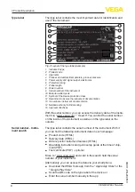
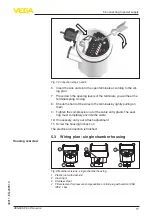
Fig. 9: Electronics and connection compartment
1 DIL switch for measuring range selection
2 Ground terminal
3 Connection terminals
4 Control lamp
For connection to a controller. The sensor is powered by the connect-
ed controller. Further information is available in chapter "
Technical
data
", "
Ex-technical data
" are available in the "
Safety information
".
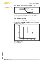
The wiring example is applicable for all suitable controllers.
Take note of the operating instructions manual of the controller. Suit-
able controllers are listed in chapter "
Technical data
".
1
Fig. 10: Wiring plan
1 Voltage supply
Electronics and connec-
tion compartment
Wiring plan


