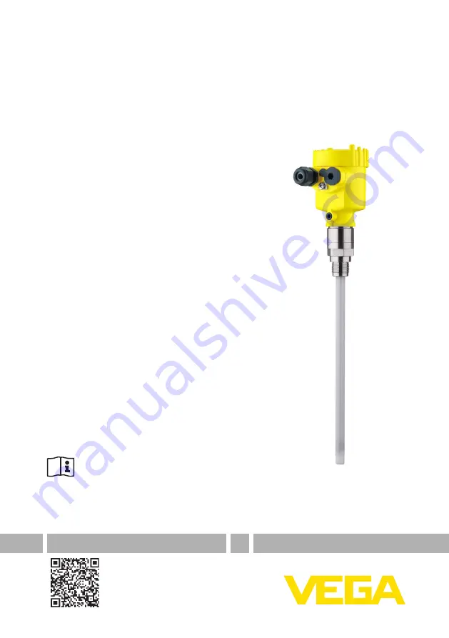
Operating Instructions
Capacitive rod electrode for level
detection
VEGACAP 63
Two-wire
Document ID: 30011
Страница 1: ...Operating Instructions Capacitive rod electrode for level detection VEGACAP 63 Two wire Document ID 30011...
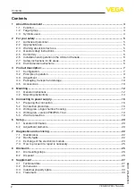
Страница 2: ...kaging transport and storage 10 3 5 Accessories 10 4 Mounting 12 4 1 General instructions 12 4 2 Mounting instructions 14 5 Connecting to power supply 16 5 1 Preparing the connection 16 5 2 Connection...
Страница 3: ...3 Contents VEGACAP 63 Two wire 30011 EN 230510 Editing status 2023 04 26...
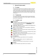
Страница 4: ...to the Docu ment ID By entering the Document ID on www vega com you will reach the document download Information note tip This symbol indicates helpful additional infor mation and tips for successful...
Страница 5: ...ct mounting or adjustment Damage to property and persons or environmental contamination can result Also the protective characteristics of the instrument can be impaired 2 4 General safety instructions...
Страница 6: ...y with the relevant requirements of the Canadian Electrical Code CEC Par I Canada 2 7 Safety instructions for Ex areas For applications in explosion proof areas Ex only devices with cor responding Ex...
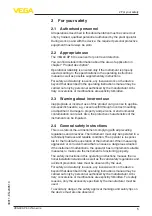
Страница 7: ...al instrument features are also described in this operating instructions manual The respective scope of delivery results from the order specification This operating instructions manual applies to the...
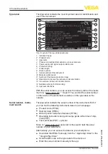
Страница 8: ...the serial number you can access the delivery data of the instru ment via www vega com Search You can find the serial number on the inside of the instrument as well as on the type label on the outsid...
Страница 9: ...the dielectric Due to the higher dielectric constant of the product compared to air the capacitance increases as the probe is gradually covered The capacitance change is converted by the electronics m...
Страница 10: ...he packages must be stored only under the following conditions Not in the open Dry and dust free Not exposed to corrosive media Protected against solar radiation Avoiding mechanical shock and vibratio...
Страница 11: ...the use of a vacuum tight version Nozzle In case of long nozzles the shielding tube can increase the sensitivity of the probe by compensating the influences of the nozzle The suit able version is Capa...
Страница 12: ...work remove the electronics module from the sensor By doing this you avoid damage to the electronics through inductive coupling Ground the probe before welding directly on the rod or cable Devices wi...
Страница 13: ...el Make sure that the mechanical connection of the probe to the vessel is electrically conductive to ensure sufficient grounding Use conductive seals such as those made of copper or lead etc Insulatin...
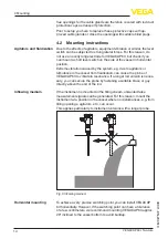
Страница 14: ...bulence in the vessel from fluidisation can cause the probe of VEGACAP 63 to vibrate in resonance If a longer rod version is neces sary you can secure the probe by fastening a suitable brace or guy di...
Страница 15: ...For that reason avoid using mounting bosses for flanges and screwed fittings This applies particularly to use with adhesive products To compensate the material specific preload loss due to sealing ma...
Страница 16: ...magnetic interference is expected which is above the test values of EN 61326 1 for industrial areas shielded cable should be used Make sure that the cable used has the required temperature resist ance...
Страница 17: ...nals by lightly pulling on them 9 Tighten the compression nut of the cable entry gland The seal ring must completely encircle the cable 10 If necessary carry out a fresh adjustment 11 Screw the housin...
Страница 18: ...ler The sensor is powered by the connect ed controller Further information is available in chapter Technical data Ex technical data are available in the Safety information The wiring example is applic...
Страница 19: ...y or to the processing system 2 Shielding 5 5 Warm up reaction After connecting to voltage supply or after a voltage recurrence the instrument passes a certain switch on routine By lowering the curren...
Страница 20: ...mode switch afterwards This could possibly trigger other connected instruments or devices 6 2 Adjustment elements 4 1 2 3 Fig 13 Electronics module Two wire output 1 DIL switch for measuring range sel...
Страница 21: ...of the Controller The adjustment of the switching point is only possible in installed condition Standing capacitances in a vessel can influence the measurement We therefore recommend to carry out a c...
Страница 22: ...r Process Voltage supply Signal processing The first measure to take is to check the output signal In many cases the causes can be determined this way and the faults quickly rectified Depending on the...
Страница 23: ...en changes the mode the probe may be mechanically damaged Should the switching func tion in the correct mode still be faulty return the probe for repair Check if there is buildup on the probe and if s...
Страница 24: ...ull out old electronics module 7 Compare the new electronics module with the old one The type label of the electronics module must correspond to that of the old electronics module This applies particu...
Страница 25: ...ee chapter Set up adjustment elements 18 Screw the housing lid back on The electronics exchange is now finished 7 4 How to proceed if a repair is necessary You can find an instrument return form as we...
Страница 26: ...ng to voltage sup ply and carry out the listed steps in reverse order 8 2 Disposal Pass the instrument on to a specialised recycling company and do not use the municipal collecting points Remove any b...
Страница 27: ...d PTFE PE Probe rod fully insulated 16 mm 0 63 in 316L Materials non wetted parts Plastic housing Plastic PBT Polyester Aluminium die cast housing Aluminium die casting AlSi10Mg powder coated Basis Po...
Страница 28: ...accuracy according to DIN EN 60770 1 Reference conditions according to DIN EN 61298 1 Temperature 18 30 C 64 86 F Relative humidity 45 75 Air pressure 860 1060 mbar 86 106 kPa 12 5 15 4 psig Deviatio...
Страница 29: ...ure 2 Ambient temperature 3 Temperature range with temperature adapter Dielectric constant 1 5 Electromechanical data version IP66 IP67 and IP66 IP68 0 2 bar Options of the cable entry Cable entry M20...
Страница 30: ...4X Aluminium IP66 IP68 0 2 bar IP68 1 bar Type 6P Type 6P Stainless steel electro polished IP66 IP68 0 2 bar IP68 1 bar Type 6P Type 6P Stainless steel precision casting IP66 IP68 0 2 bar IP68 1 bar T...
Страница 31: ...mm 2 72 79 mm 3 03 112 mm 4 41 M20x1 5 NPT 116 mm 4 57 86 mm 3 39 116 mm 4 57 M20x1 5 M20x1 5 NPT Fig 19 Housing versions in protection IP66 IP67 and IP66 IP68 0 2 bar 1 Plastic single chamber 2 Stai...
Страница 32: ...ACAP 63 Two wire 30011 EN 230510 16mm 0 63 L G G 1 G 1 56 mm 2 21 22 mm 0 86 Fig 21 VEGACAP 63 threaded version G1 ISO 228 T1 L Sensor length see chapter Technical data 108 mm 4 25 40 mm 1 58 Fig 22 T...
Страница 33: ...ter www vega com Les lignes de produits VEGA sont globalement prot g es par des droits de propri t intellec tuelle Pour plus d informations on pourra se r f rer au site www vega com VEGA lineas de pro...
Страница 34: ...34 Notes VEGACAP 63 Two wire 30011 EN 230510...
Страница 35: ...35 Notes VEGACAP 63 Two wire 30011 EN 230510...
Страница 36: ...ing scope of delivery application practical use and operat ing conditions of the sensors and processing systems correspond to the information available at the time of printing Subject to change withou...