

6
.
3
A
djustment system
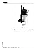
1.1
2
3
1
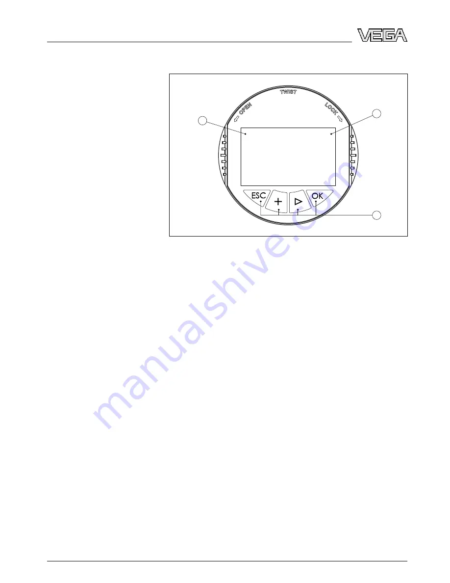
F
ig
.
12
:
I
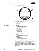
ndicating and adjustment elements
1
LC
display
2
I
ndication of the menu item number
3
A
djustment keys
l
[
OK
]
key
:
-
move to the menu overview
-
con
fi
rm selected menu
-
E
dit parameter
-
S
ave value
l
[-
>
]
key to select
:
-
menu change
-
list entry
-
S
elect editing position
l
[
+
]
key
:
-
C
hange value of the parameter
l
[
ESC
]
key
:
-
interrupt input
-
jump to the next higher menu
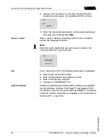
T
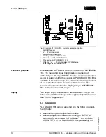
he sensor is adjusted via the four keys of the indicating and
adjustment module
.
T
he
LC
display indicates the individual
menu items
.
T
he functions of the individual keys are shown in
the above illustration
.
A
pprox
.
10
minutes after the last
pressing of a key
,
an automatic reset to measured value
indication is triggered
.
A
ny values not con
fi
rmed with
[
OK
]
will
not be saved
.
K
ey functions
A
djustment system
24
PLICSRADIO T
61
-
wireless emitting unit
(
single channel
)
S
et up with the indicating and adjustment module
32865
-
EN
-
070801
Содержание PLICSRADIO T61
Страница 45: ...Supplement PLICSRADIO T61 wireless emitting unit single channel 45 32865 EN 070801...
Страница 46: ...Supplement 46 PLICSRADIO T61 wireless emitting unit single channel 32865 EN 070801...
Страница 47: ...Supplement PLICSRADIO T61 wireless emitting unit single channel 47 32865 EN 070801...


