Vega BS/User Manual
11
Revision 10 – 02 November 2017
CONTROL INSTRUMENTS – PUSHBUTTONS AND SWITCHES
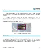
There are two buttons on the gateway board. One button is spare for further
developments (Fig. 3.1 (3)). Push the other button (Fig. 3.1 (4)) for the gateway instantaneous
rebooting.
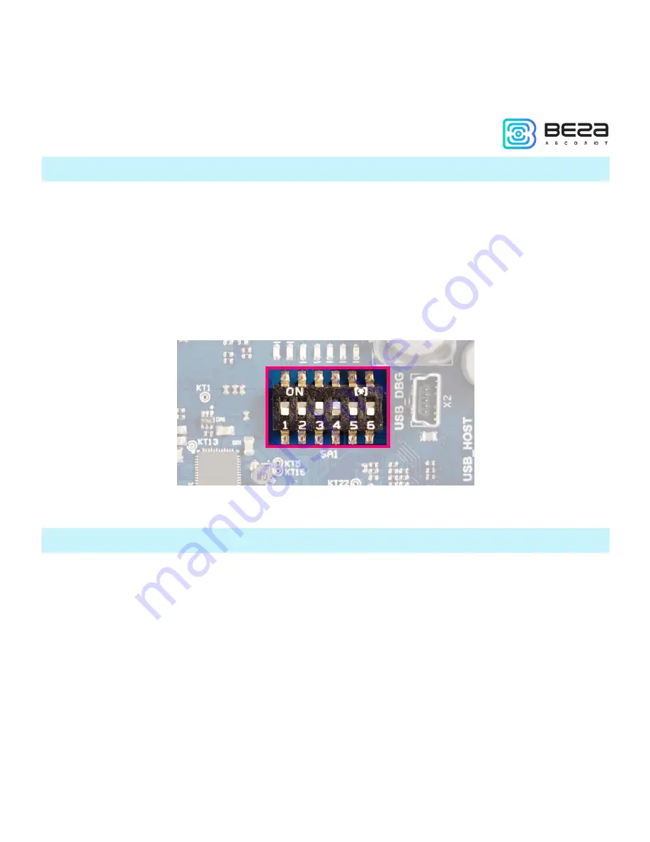
In addition, there are DIP switches (Fig. 3.1 (5)) on the board used to select the
download option of the firmware image: from internal memory, from the SD card or via mini-
USB from the computer. The switches are used only in service conditions. In operating mode,
only switches 3 and 4 shall be enabled, see fig. 3.3.
Fig. 3.3. Operating position of DIP-switches
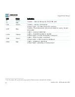
INDICATION
There are several LEDs (fig. 3.1 (6)) on the terminal board, which signals are shown in
the table below. They indicate operation of particular systems: power (on / off), visibility of
GPS satellites, GSM modem (on / off), operation of the LoRa signal processing program
(Packet forwarder on/off), Ethernet activity, the data exchange via mini USB port.


