background image

8

  Component Replacement Procedures

In non-display consoles the Ack/CPU assembly is, except for the display screen itself, essentially the same as the 
Display/CPU assembly. The Display ribbon cable connects to a different CPU board connector than the Ack 
switch panel cable plug (see Items 4 and 5 in Figure 3). Other than the GUI display and Ack switch panel 
difference, the additional removal procedures discussed in this section are identical. 

Removing Display/CPU Assembly

Avoid unnecessary contact with the CPU board components to avoid static damage to the board’s circuitry. Wear 
grounded anti-static wrist strap before handling printed circuit boards.

1.

Turn Off, tag and lockout power to the console.

2.

Remove the two T15 Torx shoulder screws under the front cover of the console (Item 6 in Figure 1). Tilt the 
bottom of the cover out as you lift it off of the two hooks in the top of the console’s housing.

3.

Using masking tape, mark each connected comm cable with the port to which each cable is attached and 
remove the comm cables.

4.

Remove the T15 #8 x 0.3125 screw (Item 4 in Figure 2) and the T20 #8 x 0.875 screw (Item 7 in Figure 2) 
securing the Display/CPU assembly to the console and set them aside. Slide the Display/CPU assembly up 
as far as it will go and tilt out the bottom of the assembly to access the short 20-pin cable connecting the 
Display/CPU assembly to the USIOM board in the console. Disconnect the cable plug from its USIOM board 
socket by pressing against the vertical locking lever in the middle of the plug as you lift it away from the socket. 

5.

The CPU board is on the underside of the Display/CPU assembly.

Removing The SD Card

1.

Follow the steps above to remove the Display/CPU or Ack/CPU assembly. 

With the Display/CPU assembly removed, set it on a clean surface, display side down. The SD card (Item 2 in 
Figure 3) is removed by pushing in gently on the end of the card and quickly releasing it so it springs free of its 
enclosure’s latch. 

2.

When replacing the SD card, always check the read/write-protect switch on the side of the card is in the 
position shown in Figure 5. Orient the card, contacts down and angled corner to the left, as you gently push 
the card into its enclosure until it clicks into the enclosure’s latch.

OFF

Содержание TLS4/8601 Series

Страница 1: ...Manual No 577014 043 Revision C Software Hardware Upgrade Replacement Manual TLS4 8601 Series Consoles...

Страница 2: ...and Conditions VEEDER ROOT S PREFERRED CARRIER 1 Contact Veeder Root Customer Service at 800 873 3313 with the specific part numbers and quantities that were missing or received damaged 2 Fax signed...

Страница 3: ...tware Maintenance Upgrade Features 20 Figures Figure 1 TLS4 8601 Series Console Dimensions 4 Figure 2 Component Locations Front Cover Removed 5 Figure 3 Component Locations Underside Of Display CPU Bo...

Страница 4: ...ed to perform installation checkout startup programming system tests troubleshooting service techniques and operations training on the designated system Wireless 2 Tall Tank Related Documents 577014 0...

Страница 5: ...safety Table 1 Miscellaneous Upgrade Replacement Kits Part No Kit 330020 742 Upgrade DL4 To TLS4 EDIM With Touch Screen 333530 002 Feature Upgrade TLS4 TLS4B TLS4c TLS4i TLS S1 DL4 330020 744 Operati...

Страница 6: ...it AC TLS4B TLS4c TLS S1 DL 330020 769 iButton Replacement Kit TLS4 TLS4B TLS4c TLS4i TLS S1 DL4 DL 330020 754 USB Back up Thumb Drive TLS4 TLS4B TLS4c TLS4i TLS S1 DL4 DL 330020 755 Replacement TLS4...

Страница 7: ...Serial number 3 Intrinsically safe wiring conduit knockout 1 top 1 bottom 4 Optional touch screen display 5 Status LEDs 6 T15 screws secure cover 2 places 7 Communication ports standard Serial ports 1...

Страница 8: ...Lithium battery battery backup 6 RS232 485 selection jumpers SERIAL 1 P1 and SERIAL 2 P2 factory set to RS232 position 7 T20 screw secures Display CPU assembly 8 Optional 6 device intrinsically safe...

Страница 9: ...ure 3 1 J36 Mode Jumper shown in Operating Mode Position 2 SD Card 3 Software Features iButton 4 Display ribbon cable connector Consoles with GUI display only 5 Ack switch cable connector J40 Consoles...

Страница 10: ...NG TERMINALS WARNING SUBSTITUTION OF COMPONENTS MAY IMPAIR INTRINSIC SAFETY INTRINSICALLY SAFE CIRCUITS ARE ALSO RATED AS CLASS 2 CIRCUITS TERMINALS ARE FOR CONNECTION TO I S TANK PROBES AND SENSORS U...

Страница 11: ...cables 4 Remove the T15 8 x 0 3125 screw Item 4 in Figure 2 and the T20 8 x 0 875 screw Item 7 in Figure 2 securing the Display CPU assembly to the console and set them aside Slide the Display CPU as...

Страница 12: ...der Replacing the Backup Battery 1 Remove the front cover of the TLS4 following step 1 and 2 of the Display CPU Assembly removal instructions on page 8 2 Locate the backup battery beneath the display...

Страница 13: ...of the USIOM board out enough to release the USIOM board from the snap on retaining post between the two I S sockets see Figure 11 9 With the USIOM board now free from the retaining post swing the rig...

Страница 14: ...TING 5A N G L 0 C Ta 50 C FOR SUPPLY CONNECTION USE WIRES RATED FOR AT LEAST 90 C RELAY 2 RELAY 1 F1 F2 5A SLO BLO F4 5A F7 EB 1 2 3 4 5 6 7 8 9 10 11 12 INTRINSICALLY SAFE WIRING TERMINALS WARNING SU...

Страница 15: ...CONNECTION USE WIRES RATED FOR AT LEAST 90 C RELAY 2 RELAY 1 RTN 12V PWR STAT PWR INT F1 F2 5A SLO BLO F4 5A SLO BLO F6 0 75A SLO BLO F7 EB25918024 2 3 4 5 6 7 8 9 10 11 12 INTRINSICALLY SAFE WIRING T...

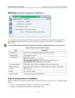
Страница 16: ...e Maintenance Activate Revert This screen lets you activate newly installed software or revert to a previously stored version of software During the activation process several dialog boxes will be dis...

Страница 17: ...ilable will display if a version of software has not been stored Current Operation Status of the console Idle no software is being installed or reverted or Activating a software install is in progress...

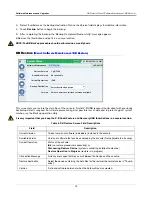
Страница 18: ...creen Field Descriptions Field Description Current Version Current version of software x xx xxx x installed in the console Available Version Not applicable to a backup Current Operation Status of the...

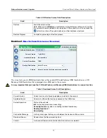
Страница 19: ...location Table 4 DB Restore Screen Field Descriptions Field Description Current Version Current version of software x xx xxx x installed in the console Available Version Version of software that can...

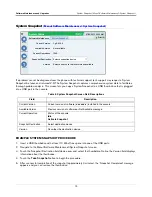
Страница 20: ...load Screen Field Descriptions Field Description Current Version Current version of software x xx xxx x installed in the console Available Version Version of software that can be accessed on the USB d...

Страница 21: ...rrent version and Available downloaded version are displayed screen shot 7 Touch the box beside the message Click to acknowledge the system will be stopped 8 Touch the Activate button to overwrite the...

Страница 22: ...bdrive Notice the Version field displays information about the thumbdrive 4 Touch the Take Snapshot button to begin the procedure 5 After successful completion of the snapshot approximately 3 minutes...

Страница 23: ...ew feature s will be required Table 7 Upgrade Features Screen Field Descriptions Field Description Feature box List features which are available to be activated Multiple features may be activated conc...

Страница 24: ...For technical support sales or other assistance please visit www veeder com...

Отзывы: