Installation Guide
Receiver Installation
24
3.
Note that the receiver cover label indicates the cord grip to be used for the RS-485 cable from the TLS
RF. Loosen that cord grip then remove the cover of the receiver and set it aside.
4.
Note that the Receiver cover label indicates the cord grip to be used for the RS-485 cable from the TLS
RF and the cable to the Repeater (if used). If you are installing a Repeater in this site, loosen both cord
grip nuts, otherwise loosen the TLS RF cord grip, then remove the cover of the Receiver and set it aside.
5.
Push the TLS RF RS-485 cable through the loosened cord grip. Strip back the jacket from the end of the
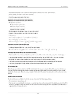
cable as shown in Figure 22. Note that there are two twisted pair color-coded wires in the cable (e.g., a
white with blue stripe and blue with white stripe pair and a white with orange strip and orange with white
stripe pair).
6.
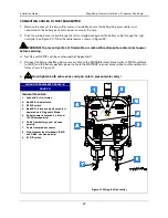
One of the pairs is for RS-485 communication (- & + terminals) and the other pair is for receiver power
(+15 Vdc & Gnd). Using Figure 24 as a guide, connect the wires of the two twisted pairs to the RS-485
terminals.
Record which wire attaches to each terminal to help you attach the other end of that wire to the identically
marked terminal in the TLS RF.
7.
Referring to your connection notes in step 5 above, connect the other end of the RS-485 cable to the RS-
485 terminal block in the TLS RF (ref. Figure 6 on page 11).
8.
If a Repeater is used and powered by the Receiver, push the two wire power cable (to Repeater) through
the +15 Vdc cord grip of the Receiver. Strip back the jacket from the end of the cable as shown in Figure
22. Attach the dc power cable (white to +15 and black to GND) to the Repeater terminal block (item 9 in
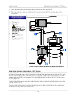
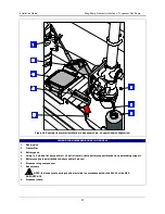
LEGEND FOR NUMBERED BOXES IN FIGURE
1.
Receiver or repeater
2.
0.280” diameter hole (2) – mount this
narrow side of bracket to wall or post
3.
Mounting bracket
4.
#10 x 1/2” taptite screws
Receiver is only suitable for use in and
over a non-hazardous location.
Figure 23. Attaching mounting bracket to receiver or repeater
9.
Set S1 and S2 DIP settings as desired (ref. Appendix C).
10.
Hand tighten both cord grip nuts to prevent water entry!
11.
To assure a water-tight seal between the cover and the enclosure, follow these steps:
a. Insert the four cover screws through the cover and then press on the retaining washers to hold the
screws in place.
b. Make sure that the cover gasket is free of dirt and debris on both sides of the gasket and that the inside
of the cover is clean in the gasket area.
c. Position the gasket into the cover groove, assuring that it is pressed fully into the groove and sitting
completely flat.


